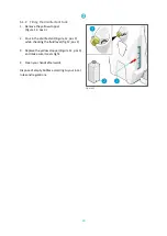
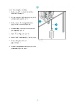
background image


23 


6.1.2


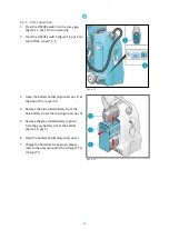
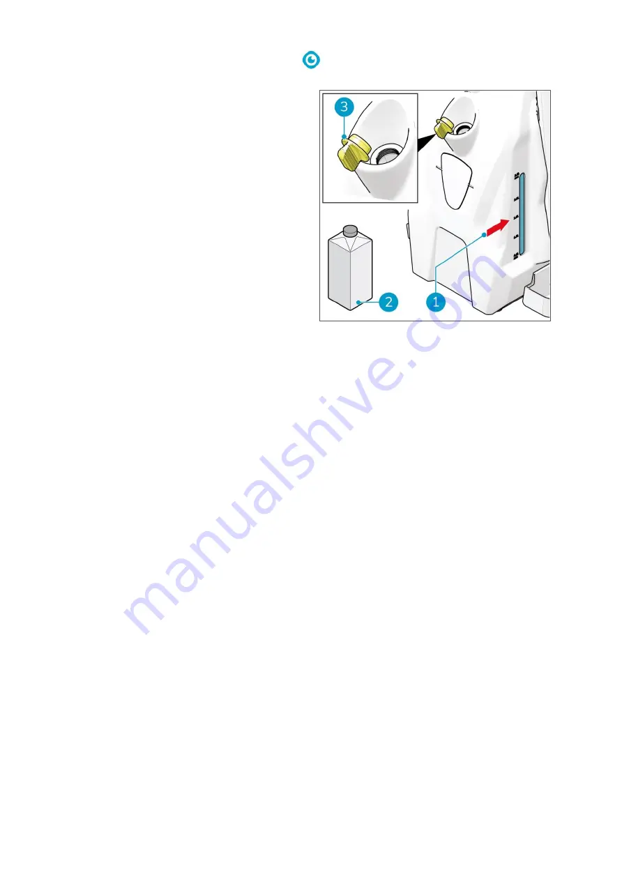
Filling the disinfectant tank 

1.


Remove the yellow stopper  
(Figure 12, pos 3). 
 

2.


Pour in the disinfectant (Figure 12, pos 2) 
while checking the fluid level (fig 12, pos 1). 
 

3.


Replace the yellow stopper (Figure 12, pos 3) 
and make sure it seals tight. 
 

4.


Clean your hands afterwards. 
 

Dispose of empty bottles according to your local 
rules and regulations. 


Figure 12 


Summary of Contents for i-cover 2.5

Page 1: ...team Professional b v Hoppenkuil 27b 5626 DD Eindhoven The Netherlands Telephone 31402662400 Email hello i teamglobal com Internet www i teamglobal com i cover 2 5 Rolling disinfectant sprayer User manual ...

Page 2: ...nguage Future Cleaning Technologies B V Hoppenkuil 27b 5626 DD Eindhoven The Netherlands Telephone 31402662400 Email hello i teamglobal com Internet www i teamglobal com Model I COVER 2 5 24V Date 19 01 2021 Product code IM25 FCT 1115B Version v 1 0 ...

Page 3: ... care and caution maintained with manufacturer supplied parts When this manual refers to the manufacturer this means Future Cleaning Technologies B V an affiliate company of i team in Eindhoven the Netherlands When this manual mentions the partner your local i team resell and support service partner is referred to Purpose of the user manual The purpose of the user manual is to provide the user wit...

Page 4: ... or the environment BATTERIES Indicates a battery operated machine batteries must be charged according to the instructions in the separate Class I Battery Charger user manual Batteries must be disposed of according to your local laws and regulations ATTENTION Indicates a liability situation where the manufacturer or its partners and affiliates cannot be held accountable for damages caused by non c...

Page 5: ...trol panel on the spay gun 14 2 3 Spray nozzles and nozzle filter 14 3 Safety 15 3 1 General safety instructions 15 3 2 Risks during operation 15 3 2 1 The disinfectant 15 3 2 2 The batteries 15 3 2 3 Personal protection 16 4 Transport and storage 17 5 Assembly and installation 18 5 1 Unboxing 18 5 2 Trolley or backpack operation 19 5 2 1 Trolley operation 19 5 2 2 Backpack operation 21 6 Operatio...

Page 6: ...e 30 6 4 Cleaning and storage 30 6 4 1 Cleaning the body of the i cover 2 5 30 6 4 2 Flushing the spray nozzle 30 6 4 3 Draining the machine 31 6 4 4 Cleaning with water 32 6 4 5 Removing the batteries 33 6 4 6 Storage 33 7 Maintenance 34 8 Troubleshooting 35 9 Decommissioning and disposal 36 10 Attachments 37 10 1 CE Certificate 37 ...

Page 7: ...cedure This manual is intended for those who work with the i cover 2 5 and perform daily maintenance The manual must be read in full before the first actions This manual describes the correct method of use safety measures maintenance and transport And finally the manual contains information about the consumables the disinfectant the color coded spray nozzles i team continuously improves all their ...

Page 8: ...nozzle away from your face as the disinfectant can blow out vapors that can cause irritation Always check the recommendations written on the packaging of the disinfectant that you use Use your favourite disinfectant solution at the appropriate dilution specified on the product label if applicable Disinfectants for which a dilution is needed that carries a corrosive pictogram GHS05 or the hazard st...

Page 9: ...ed use can have consequences for the safety of operators and bystanders and will void the warranty on the product The i cover 2 5 is not intended to disinfect anything else than surfaces 1 3 Lifespan CAUTION To ensure proper and safe operation throughout the life of the i cover it is recommended to have an authorised i team partner check the machine after the first 50 hours of use and then every 1...

Page 10: ... i power 9 24 V 8 8 Ah Battery spec i power 14 25 2 V 14 Ah Run time i power 9 11 hours Run time i power 14 18 hours Material PP Vibration main body handle Amplitude 0 008 0 021 mm Velocity 0 9 2 0 mm s Acceleration 0 7 0 7 m s Flow speeds 0 2 mm spray nozzle 25 ml min 0 3 mm spray nozzle 35 ml min 0 5 mm spray nozzle 70 ml min 0 8 mm spray nozzle 100 ml min Sound level 1 m distance and 1 m distan...

Page 11: ...cover 2 5 should only be operated with the materials supplied Using alternative supplies may cause damage to the i cover 2 5 and may cause a risk to the operator The use of alternative supplies voids manufacturer s warranty ...

Page 12: ...fication number that can be found on the top of the main body Your i team dealer needs this number when you order parts Product type i cover 2 5 Serial number Current 24 V power 45 W Distributer i team Professional Hoppenkuil 27 b NL 5626 DD Eindhoven Figure 3 ...

Page 13: ...ant tank can be carried as a backpack or as trolley or by hand the spay gun with the spray nozzle The i cover 2 5 consists of Figure 4 Legend 1 A trolley 7 A spray nozzle 2 A battery hatch 8 A nozzle filter 3 A disinfectant tank 9 An extension tube 4 A main body 10 A spray gun 5 A control panel 11 A harness 6 A hose ...

Page 14: ...Figure 5 pos A will show a 1 this indicates 1 hour The counter on the right Figure 5 pos B starts again at 1 3 The ON OFF switch 2 2 Control panel on the spay gun 1 The ON OFF switch on the spray gun 2 3 Spray nozzles and nozzle filter Spray nozzle diameter and color Intended spaces 0 2 mm x 1 yellow ring Fragile or sensitive objects 0 3 mm x 1 green ring Indoor applications 0 5 mm x 1 orange ring...

Page 15: ...orrosive to metals or H314 Causes severe skin burns and eye damage The use of these type of disinfectants should generally be avoided Refer to the product s in use concentration SDS sheet WARNING General safety rules keep locked up and out of reach of children keep away from food drink and animal feed when ingested seek medical advice immediately and show the bottle DO NOT induce vomiting 3 2 2 Th...

Page 16: ... The disinfectant can be irritating to the eyes Wear eye protection and use caution when filling Always keep the spray nozzle pointed away from your face ATTENTION Clean your hands immediately after filling or draining the disinfectant tank ...

Page 17: ...before you store or transport the i cover 2 5 it is recommended to drain it store the steam lance in its holder during transport and storage before you store the i cover 2 5 it is recommended to clean the it with a damp cloth do not store the i cover 2 5 outdoors store the i cover 2 5 in an upright position and in a dry place in case the i cover 2 5 is stored for a longer period remove the batteri...

Page 18: ...tery charger can be ordered separately 5 1 Unboxing The i cover 2 5 is packed in 1 box Figure 7 Legend 1 1x trolley 6 1x nozzle filter 2 1x disinfectant tank 7 4x spray nozzle 3 1x i cover 2 5 main body 8 1x accessory box 4 1x hose with spray gun 9 1x harness 5 1x extension tube 10 1x this manual ...

Page 19: ...operation When you use the i cover 2 5 as a trolley it is advised to remove the harness so loose straps cannot be caught between the wheels To remove the harness 1 Remove the padding Figure 8 pos 1 that is attached to the back plate with Velcro Figure 8 ...

Page 20: ...20 2 Unscrew the four screws Figure 9 pos 2 using a Philips screwdriver 3 Remove the back plate Figure 9 pos 1 Figure 9 ...

Page 21: ...k in place as these also hold the trolley handle Figure 10 pos 1 Figure 10 5 2 2 Backpack operation When you use the i cover 2 5 as a backpack no further assembly is required TIP Keep all removed parts safely stored for future use ...

Page 22: ...pos 2 at the side of the i cover 2 5 2 Place the blue coded battery in the blue battery slot at the top Figure 11 pos 3 3 Place the gray coded battery option in the gray battery slot at the bottom Figure 11 pos 1 4 Close the battery holder Figure 11 pos 2 5 Press the ON OFF switch below the battery holder to turn on the i cover 2 5 6 Check the battery indicator next to the main switch See also sec...

Page 23: ... pos 3 2 Pour in the disinfectant Figure 12 pos 2 while checking the fluid level fig 12 pos 1 3 Replace the yellow stopper Figure 12 pos 3 and make sure it seals tight 4 Clean your hands afterwards Dispose of empty bottles according to your local rules and regulations Figure 12 ...

Page 24: ...ic job Please see section 2 3 All spray nozzles can be used in combination with the nozzle filter Normal use 1 Turn the spray nozzle clockwise to attach it to the spray gun Figure 13 pos 1 Extended reach 1 Turn the extension tube clockwise to attach it to the spray gun Figure 13 pos 3 2 Turn the spray nozzle clockwise Figure 13 pos 2 to attach it to the extension tube Figure 13 ...

Page 25: ...to spray 2 Press the ON OFF switch Figure 14 pos 1 to turn on the i cover 2 5 The hour meter and the battery power status display light up See also section 2 1 3 Press the ON OFF switch on the spray gun Figure 14 pos 2 4 Start working with the i cover 2 5 Figure 14 ...

Page 26: ...der Figure 16 pos 2 at the side of the i cover 2 5 4 Remove the blue coded battery from the blue battery slot at the top Figure 16 pos 3 5 Remove the gray coded battery option from the gray battery slot at the bottom Figure 16 pos 1 6 Close the battery holder Figure 16 pos 2 7 Charge the batteries for next use please refer to the user manual of the i charge 2 or i charge 9 Figure 15 Figure 16 ...

Page 27: ...straps Figure 17 pos 1 of the harness to their maximum size 2 Remove the spray gun and place it on a chair or table 3 Put on the backpack 4 Adjust the waistband Figure 17 pos 2 and the straps Figure 17 pos 1 so they fit comfortably Figure 17 ...

Page 28: ...Press the ON OFF switch Figure 18 pos 1 to turn on the i cover 2 5 The hour meter and the battery power status display light up See also section 2 1 7 Press the ON OFF switch on the spray gun Figure 18 pos 2 8 Start working with the i cover 2 5 Figure 18 ...

Page 29: ... 3 to turn off the i cover 2 5 4 Open the battery holder Figure 20 pos 2 at the side of the i cover 2 5 5 Remove the blue coded battery from the blue battery slot at the top Figure 20 pos 3 6 Remove the gray coded battery option from the gray battery slot at the bottom Figure 20 pos 1 7 Close the battery holder Figure 20 pos 2 8 Charge the batteries for next use please refer to the user manual of ...

Page 30: ... batteries 6 4 1 Cleaning the body of the i cover 2 5 Wipe the body of the i cover 2 5 after each use 6 4 2 Flushing the spray nozzle To prevent blockage of the spray nozzle it is recommended to flush the spray nozzle with tap water after each use Or use an ultrasonic cleaner 1 Remove the spray nozzle see section 6 3 2 2 Flush the spray nozzle Figure 21 pos 1 with tap water 3 Place the spray nozzl...

Page 31: ...gure 22 pos 3 3 Put the end of the drainage tube into a proper container for disinfectants 4 Remove the yellow stopper from the fluid tank Figure 12 pos 2 5 Open the tap Figure 22 pos 2 6 When empty close the tap Figure 22 pos 2 7 Replace the yellow stopper Figure 12 pos 2 8 Replace the drainage tube Figure 22 pos 1 using clips Figure 22 pos 3 Figure 22 ...

Page 32: ...me water to come out to clean the nozzle 6 Press the ON OFF button on the spay gun Figure 23 pos 2 7 Press the ON OFF button on the body of i cover 2 5 Figure 19 pos 3 to turn it off 8 Put the i cover 2 5 on a table with the backside towards you 9 Release the drainage tube Figure 22 pos 1 via the clips Figure 22 pos 3 10 Open the tap Figure 22 pos 2 11 Put the end of the drainage tube into a prope...

Page 33: ...ery from the blue battery slot at the top Figure 24 pos 3 3 Remove the gray coded battery option from the gray battery slot at the bottom Figure 24 pos 1 4 Close the battery holder Figure 24 pos 2 5 Charge the batteries for next use please refer to the user manual of the i charge 2 or i charge 9 6 4 6 Storage See section 4 Figure 24 ...

Page 34: ...e To ensure proper and safe operation throughout the life of the i cover 2 5 it is recommended to have an authorized i team partner check the machine after the first 50 hours of use and then every 125 hours afterwards ...

Page 35: ...to reinsert the battery correctly until you hear a click Fluid leakage Filler cap is not put back correctly Check and replace the filler cap correctly Drain connector cap is not put back correctly Check and replace the drain connector cap correctly i cover 2 5 was stored or transported lying down without draining the tank first Place the i cover 2 5 upright Battery not charging Battery is end of l...

Page 36: ...recycling of electrical equipment Before disposal please 1 Remove the batteries for separate disposal 2 Empty the disinfectant tank 3 Remove all loose components like spray nozzles the belt and carrying handle 4 Dispose all items according to your local laws and regulations TIP Alternatively keep the batteries for use in another piece of i team equipment TIP Contact your local i team partner to ex...

Page 37: ...37 10 Attachments 10 1CE Certificate ...

Page 38: ...38 This document is part of the technical file of the i cover 2 5 and will be available upon request ...

Reviews: