16
2.1.2
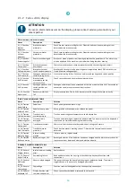
Codes alarm display
ATTENTION
In case an alarm code occurs on the display, please contact service personnel or your
i-team partner.
Alarm summary table control panel
Alarm
Description
Solution
AL_1: Function
Brushes
Ammeter
Brushes ammeter
protection.
Check brushes motor working current. Excessive and continuous working current
detected on the brushes motor.
AL_2: Function
Vacuum
Ammeter
Vacuum ammeter
protection.
Check vacuum motor working current. Excessive and continuous working current
detected on the brushes motor.
AL_3: Function
Power stage Fail
Power circuit damaged.
Brushes or vacuum power circuit damaged: replace the power board. The alarm may
also be displayed if the machine is started when being towed or moving.
AL_4: Function
Overcurrent
Brushes or vacuum
overcurrent.
Short circuit on brushes or vacuum motor detected: check wirings and motors.
AL_5: Function
Overtemperature
Brushes or vacuum
circuit overtemperature.
Brushes and vacuum circuit power stage overtemperature: check if disc brushes run
freely. Measure voltage output.
AL_7: Function
Act2 endsw fail
Squeegee actuator limit
switch reading failure.
Limit switch setting failure. Check connections and squeegee end switch position.
AL_8: Function
Act1 timeout
Brush actuator
movement over the
time limit (12s):
Check connections and any mechanical obstructions.
AL_9: Function
Act2 timeout
Squeegee actuator: end
switch position not
reached.
Squeegee actuator position not reached within the maximum time set. Check actuator
connections and/or any mechanical obstructions.
AL_11: Function
Water Level
Recovery water tank
full.
Empty recovery tank. Check if the recovery tank floating switch works correctly.
“DRIVE” ALARM SUMMARY TABLE
Alarm
Description
Solution
AL_13: Traction
Pedal Failure
Pedal tear.
Check pedal potentiometer wirings.
AL_14: Traction
Release Pedal
Pedal active at power
on.
Moving switch active at power on: release the pedal.
AL_15: Traction
Overtemperature
Traction circuit
overtemperature.
Traction power stage overtemperature: check absorption.
AL_16: Traction
Power stage Fail
Traction circuit
damaged.
Traction circuit damaged: replace the power board. The alarm may also be displayed if
the machine is started when being towed or moving.
AL_17: Traction
Overcurrent
Traction overcurrent.
Short circuit on traction motor detected: check wirings and motors.
AL_18: Traction
Tract. Ammeter
Traction ammeter
protection.
Check traction motor's working current. Traction motor excessive overcurrent
detected.
AL_19: Traction
Motor Voltage
Internal reading
mistake.
If failure persists, replace board.
AL_24: Traction
Batt connection
Battery voltage < 10V.
Recharge batteries. If the batteries have been charged and the alarm occurs, check for
loose connections between battery and electronic board.
“GENERAL” ALARM SUMMARY TABLE
Alarm
Description
Solution
AL_20: General
EEprom Failure
Internal eeprom reading
error.
Replace board.
AL_21: General
Key-off failure
Key-reading failure.
Rebound detected on the key signal: check battery-keyboard-function card
connections.
AL_22: General
Main relay
failure
General relay damaged.
The general relay on the board looks damaged: replace the board. The alarm is
triggered even in the event of a damaged power fuse.
AL_23: General
Overvoltage
Overvoltage.
Function card overvoltage detected. Check battery connections.
AL_25: General
Keyboard fail
Display-function card
communication error.
Check connections between display and function card.


