background image

Console User

s Manual


38

4.11 On Screen Display Operation 

1. OSD menu can be popped up in powered on PC port or non-powered on PC port or empty 

PC port. The resolution of OSD menu is fixed to 1024X768 for non-powered on PC port or 

empty PC port. 

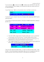
2. When you pop up the OSD menu window go through the hot key, you will see the following 

small window on your monitor. 


a.


The 1      line bar is Bank no. 

b.


The 2


block is your PC system name list. You will find the system number list from 

01 to 04 (if the current box is 4 port) or from 01 to 8 (if the current box no. is 8 port)or 

from 01 to 16 (if the current box no. is 16 port). You can define your PC name in 

maximum 8 characters. The factory default of 16 port Console PC name is from   

SYSTEM  01

, SYSTEM 02

,

,

SYSTEM 16

 and 8 port Console is from 

SYSTEM  

01

SYSTEM 02

,

,

SYSTEM 08

. Besides, the sun symbol 

near to the PC 

system is powered on. 

01


SYSTEM  01    

02


SYSTEM  02


03


SYSTEM  03    

04


SYSTEM  04 

05


SYSTEM  05    

06


SYSTEM  06 

07

        SYSTEM    07       

08


SYSTEM  08 

09

        SYSTEM    09       

10


SYSTEM  10 

11


SYSTEM  11    

12


SYSTEM  12 

13

        SYSTEM    13       

14


SYSTEM  14 

15


SYSTEM  15    

16


SYSTEM 16 

BANK : 

OSD : 

10


SEC.      CHANGE PASSWORD


SCAN : 

10


SEC.      CONSOLE 

ON

/OFF


ESC : QUIT                          ENTER : COMPLETE 

TAB : NEXT                        INSERT : EDIT 

©

 / 

ª

 : PORT SELECT   

PgDn/PgUp : BANK SELECT 

st 

st 

Summary of Contents for DKP-115 Series

Page 1: ...er cord such a way that people can not step on it Do not place anything over power cord The power cord must rate for the voltage and current marked on the product s electrical ratings label The voltage and current rating of the cord should be greater than the voltage and the current rating marked on the product 11 All cautions and warning on the equipment should be noted 12 If the equipment is not...

Page 2: ......

Page 3: ......

Page 4: ...onsole user s manual 4 4 6 Product Details 32 4 7 Hardware Installation 32 4 8 Usage 33 4 9 Daisy Chain Connection Diagram 36 4 10 Hot Plug 37 4 11 On Screen Display Operation 38 4 12 Troubleshooting 41 ...

Page 5: ... images with clear definition even at high resolutions The KVM Console monitors are intelligent microprocessor based and have an ergonomically designed display The KVM Console monitors employ the latest in active matrix thin film transistor TFT technology providing crisp screen images and wide viewing angles Unlike CRT monitors LCD monitors are inherently immune to the magnetic fields commonly fou...

Page 6: ......

Page 7: ......

Page 8: ......

Page 9: ......

Page 10: ......

Page 11: ......

Page 12: ......

Page 13: ......

Page 14: ......

Page 15: ......

Page 16: ......

Page 17: ......

Page 18: ...rast Color Position Language Recall Exit 3 Press the menu bottom to enter and you will see VGA DVI 4 Use the Down and Up bottom to select the input source of signal 5 Press the menu bottom to enter Controls Description Soft power on off button Adjacent LED is lit when on Auto Auto synchronize and scale down display to any valid factory preset timings Up Press to scroll the function you want to adj...

Page 19: ...htness of the display 5 Press the menu bottom to enter 2 4 Contrast 1 Press the menu bottom 2 Use the Down and Up bottom to scroll Auto tune Input Source Brightness Contrast Color Position Language Recall Exit 1 Press the menu bottom to enter 2 Use the Down and Up bottom to adjust the contrast of the display 3 Press the menu bottom to enter 2 5 Color 1 Press the menu bottom 2 Use the Down and Up b...

Page 20: ...Down and Up bottom to adjust the color of the display 5 Press menu to enter 2 6 Position 1 Press the menu bottom 2 Use the Down and Up bottom to scroll Auto tune Input Source Brightness Contrast Color Position Language Recall Exit 3 Press the menu bottom to enter And you will see Icon Description Image Pos To adjust the position of the image OSD Pos To adjust the position of the OSD Return To exit...

Page 21: ...l 5 Press the menu bottom to enter 2 8 Recall 1 Press the menu bottom 2 Use the Down and Up bottom to scroll Auto tune Input Source Brightness Contrast Color Position Language Recall Exit 3 Press the menu bottom to enter and you will see Yes No 4 Select Yes bottom then Menu bottom to recall the factory setting Select No to return to the previous page 2 9 Exit Press the exit bottom to quit OSD menu...

Page 22: ...Console user s manual 22 RED STANDBY RED SUSPEND RED OFF Note OSD On Screen Display ...

Page 23: ...e installation make sure all peripherals and computer have been turned off 3 The standard brackets are for 504 1000mm distance means front bracket to rear bracket cabinet contact your dealer if you need more longer rear brackets 3 1 2 Hardware Kits Contents 1 Rail with front and rear bracket x 2 Please identify the brackets Right and left sides are different For rack depth 504 828mm 2 Long bracket...

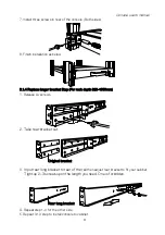
Page 24: ...o fit your cabinet 2 Install front and rear bracket on cabinet 3 Tight up four rear screws 4 Repeat step 1 3 for the other side 5 Push console into left and right rails Be careful when take out console 6 Unlock and pull rail lock switch left and right at the same time then push console to the end rail lock switch ...

Page 25: ...p For rack depth 828 1000mm 1 Release six screws 2 Take rear bracket out 3 Input rear long bracket to rear of the rail then adjust rear bracket to fit your cabinet Tight up 2 3 screws upon the length you need One is forbidden 4 Repeat step 1 3 for the other side 5 Repeat 3 1 3 step to install console to cabinet Rear long bracket Original bracket ...

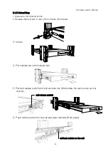
Page 26: ...crews in rear of the console Both sides 3 Unlock 4 Pull console out until console lock 5 Pull rail release switch and pull console out Both sides Be careful when pull out console 6 Push rail lock switch on the rail and push rail back Both sides rail release switch rail lock switch on the rail ...

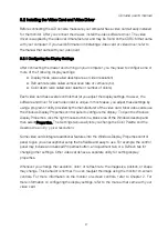
Page 27: ... cases you adjust these settings by using a program or utility provided by the manufacturer of the video card Most video cards use the Windows Display Properties control panel to configure the display To open the Windows Display Properties click the right mouse button in a blank area of the Windows desktop and then select Properties The Settings tab usually lets you change the Color Palette and th...

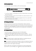
Page 28: ...momentary on off switch and the unit should power on The LED on the left of the monitor panel should turn from orange to green verifying that the unit is operational 3 4 Testing the Drawer To test that the drawer is working properly perform the following steps 1 Power up the monitor keyboard drawer and then turn on your computer 2 Make sure the video image is centered within the screen area Use th...

Page 29: ...Console User s Manual 29 make sure that all the devices on the installation are properly grounded Consult your direct vendor for any technical issues if necessary ...

Page 30: ...Intellimouse Explorer Logitech Net Mouse or the other fully compatible MS mouse z Support Win98 98SE ME 2000 XP WinNT HP Unix Linux Sun Solaris MAC O S 8 6 or later version z Manage multiple PCs G3 G4 MACs iMACs SUN Microsystems with USB port from one USB keyboard USB Mouse and Monitor z Hot Plug Add PCs or Remove Connected PCs for Maintenance without Powering Down the KVM switch or PCs z Very Hig...

Page 31: ...an Intervals 5 99 Sec Keyboard Emulation PS 2 Mouse Emulation PS 2 VGA Resolution 1920X1440 Bandwidth 200MHz Daisy Chain MAX Level 8 levels 4 4 System requirements Model No 8 port Rack Mount Console Computer side 8 HDDB 15 pin male to one HDDB 15 pin male and Mini Din 6 pin special cables Model No 16 port Rack Mount Console Computer side 16 HDDB 15 pin male to one HDDB 15 pin male and Mini Din 6 p...

Page 32: ...dware Installation Before installation please make sure all of peripherals and computers have been turned off This example of installation is based on 8 port console and you also can think that 1 port or 16 port console have the same installation procedures Step 1 Each PC port ocnnector is HDDB 15 pin type Locate your input cable It will have a HDDB 15 Pin male connector at one end Plug it into an...

Page 33: ...Console unit and plug the other end into an electrical receptacle Now you will see the LED for port 1 light up and you will hear a beep Switch on your monitor 4 8 Usage The power on state of 8 16 port KVM switch When you power on KVM switch it will ask you the password the default password value is eight zero 00000000 Please key in eight zero and enter the same value at retype field The rear side ...

Page 34: ...thin 2 seconds You will hear a beep for confirmation and the keyboard is in hot key mode If you have not pressed any key in hot key mode within 2 seconds It means to key in any key follows up Scroll Lock Scroll Lock key the keyboard will back to under Operation System control state Below are the different hot key commands Scroll Lock Scroll Lock Scroll Lock Scroll Lock Scroll Lock Scroll Lock Scro...

Page 35: ...ank 1 8 Port No 0 or 1 Port No 1 8 8 port 1 16 16 port Scroll Lock Scroll Lock Scroll Lock Scroll Lock R Space Bar Beeper Note The default Beeper function is ON and beeper control is only for available for Scan Mode Auto Scan Note This function is just for power on PC PORT OSD setting back to factory default value Note Not including password Scroll Lock Scroll Lock F On Screen Display Menu Search ...

Page 36: ...se the attached 1 8m 3 in one daisy chain Cable Kit to daisy chain the KVM Switch A Use one end of 3 in one Cable Kit to connect the daisy chain port on the Console and the other end for the console port silver color block of bank 2 KVM switch B Please repeat item A to daisy chain more bank as you want But the maximum daisy chain bank is eight levels Note If you would like to daisy chain 8 port an...

Page 37: ...e console port is connected to PC directly is powered on Before you go hot plug function please switch to this pass through port to next port or say emulation port and then switch back to the pass through port c You may unplug the mouse or the keyboard from the console port and plug it back in at any time Note Some O S Operation Systems like SCOUnix are unable to support Hot Plug function If you a...

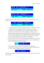
Page 38: ...rt or from 01 to 8 if the current box no is 8 port or from 01 to 16 if the current box no is 16 port You can define your PC name in maximum 8 characters The factory default of 16 port Console PC name is from SYSTEM 01 SYSTEM 02 SYSTEM 16 and 8 port Console is from SYSTEM 01 SYSTEM 02 SYSTEM 08 Besides the sun symbol near to the PC system is powered on 01 SYSTEM 01 02 SYSTEM 02 03 SYSTEM 03 04 SYST...

Page 39: ...from 05 sec to 99 sec The factory default value is 10 sec b The SCANTIME means that scan interval from one PC port to next PC port The default SCAN time is 10 sec and the maximum scan time is 99 sec c The CHANGE PASSWORD is for user to avoid all PC systems to be intruded by the other person The default password is 8 digits 00000000 There is an enter password window showed out when you select this ...

Page 40: ...Besides if current CONSOLE is ON state and you reset KVM switch the CONSOLE will be set up ON state back to OFF state e When you finish the set up of PC name and get out of OSD setting mode you will find the PC name showed at the up left corner of monitor Now you can use ESC key to clear the message right away if you don t need it f If you want OSD returning back to factory default value you can e...

Page 41: ...wise it might cause the keyboard error or keyboard is not detected at PC side 5 The computer boot up fine but keyboard doesn t work z Make sure the keyboard works when directly plugged into the computer z Try a different keyboard but use only 101 102 or 104 key keyboard 6 The Mouse is not detected during PC boot up z Make sure the mouse works when directly plugged into the computer z Make sure the...

Reviews: