OPERATION
Controlling your computers with the JKP1 series couldn
’
t be easier. The JKP1 series allows you to
access the computers using three simple methods:
Hot Keys
Manual Selectors
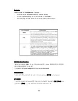
OSD (On Screen Display) Menu
PC Manual Selectors
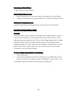
You can select any computer or access any Bank by using the PC selectors located at the top left of the
console draw.
Manual Selectors
You can directly select any single computer or access any connected Bank by using direct-access PC
selectors located at the top left of the KVM console. Each port switch has a corresponding LED for easy
status monitoring. A Green LED indicates current port selection (Selected). A Red LED light indicates a
port is not selected but the connected computer is powered and ready (Online). The JKP1 series is also
equipped with seven-segment LCD display for BANK identification when cascading.
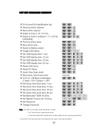
HOT KEYS
Port Identification
Each computer in a JKP1 installation has a specific port ID. You can directly switch the KVM focus to any
computer by entering the switch port number and the BANK number (for cascaded installations). Each is
assigned a two-digit numeric ID.
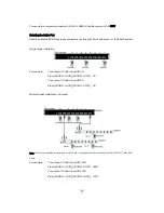
Single Switch Installation
The Port number (X) is a two-digit number that identifies the port on the JKP1 KVM switch
that the computer is connected to.
For example, a computer connected to Port 8 has the numeric ID of 08.
Multiple Switch Installation (Cascading)
The Port number (X) is a two-digit number that identifies the port on the KVM switch that the
computer is connected to.
The BANK number (Y) is a two-digit number that identifies the Switch’s position in the
cascade installation. (Note: the BANK number always precedes the Port number.)


