background image


i-Tech Company, LLC    www.i-techcompany.com 

16

Hot Plug


The KVM Switch supports “Hot Plug“ function for easy addition or removal of PCs. The user 
can arrange or maintain PCs as follows: 
a.  A PC can be disconnected and reconnected to the same or different port of the KVM 

unit without having to power it off as long as it is not the Daisy-chain port or pass 
through port. 

b.  The pass through port PC (i.e. The pass through port means the console port is 

connected to PC directly) is powered on. Before you go hot plug function, please switch 
to this pass through port to next port (or say emulation port ) and then switch back to the 
pass through port.   

c.  You may unplug the mouse or the keyboard from the console port and plug it back in at 

any time. 


N

OTE

Some O.S. (Operation Systems) like SCO Unix are unable to support “ Hot Plug ” function. If 
you apply “Hot Plug” to this kind of O.S., it will cause unpredictable behavior or shut down 
the PC. Before attempting to use “ Hot Plug ” , please make sure your O.S. and mouse 
software driver supports the “Hot Plug” function.


Troubleshooting 

1.  Ensure that all cables are well seated. Label all of cables with the number for each 

respective computer to avoid confusion. 

 
2.  The recommended VGA cable distance is 5 meters maximum without ghosting and 

degradation. Normally, the cable length is based on driver capacity of your VGA card. If 
you need longer VGA cable, please use VGA extender (Model No. VGA-100, MAX. 
100) to accomplish your applications. 

 
3.  The recommended PS2 cable distance is 5 meters maximum. Normally, the cable 

length is based on driver capacity of your motherboard PS2 port. If you need longer 
PS2 cable, please use PS2 extender ( Model No. PS-100, MAX. 100 feet) to 
accomplish your applications. 

 
4.  The Power Jack polarity is center positive and the power adapter need be DC12V, 1A 

or DC9V, 1A.   

 
5.  Don’t press any keys on the keyboard while the selected computer is booting up. 

Otherwise, it might cause the keyboard error or keyboard is not detected at PC side. 

6.  The computer boot up fine, but keyboard doesn’t work 


Make sure the keyboard works when directly plugged into the computer. 

Summary of Contents for WKP120 Series

Page 1: ...www i techcompany com Phone 888 483 2418 Fax 510 372 2736 sales i techcompany com Rev 1 0 WKP120 Series 1U Rackmount KVM Switch USER MANUAL...

Page 2: ...ODUCTION 2 FEATURES 2 PACKAGE CONTENTS 3 TECHNICAL SPECIFICATIONS 4 LCD Monitor SPECIFICATIONS 4 SYSTEM REQUIREMENT 6 CABLE DIAGRAMS 6 INSTALLATION 7 LCD MONITOR OSD Setting 9 Touch Pad 10 KVM Switch...

Page 3: ...Net Mouse or the other fully compatible MS mouse Support DOS Win3 X Win95 98 98SE 2000 ME XP WinNT Netware Unix Linux Support iMAC Power MAC and Sun Microsystems with USB port Need work with USB PS2...

Page 4: ...S User s manual 1 PCS AC to DC Power Adapter 1 PCS Rack Mount Kit 1 SET CB K15P Cable options 0 SET CB K15UP Cable options 0 SET Model No WKP120 16e 16 port Slim Rack Mount KVM Switch 16 port PS2 Cont...

Page 5: ...le Type VGA DB 15pin For test only PS 2 2 Keyboard Mouse PC selection On Screen Display Manual Hot Key On Screen Display Control Yes Scan Intervals 5 99 Sec Keyboard Emulation PS2 Mouse Emulation PS2...

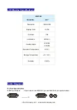
Page 6: ...1 Resolution 1600x1200 Display Color 16 7M Contrast 700 Luminance 250cd Viewing Angle H 85 85 V 85 85 Operation Temperature 0 50 Storage Temperature 20 60 Humidity 8 95 Cable Diagrams PC Port Special...

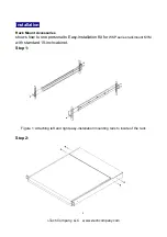
Page 7: ...tallation Rack Mount Accessories shows how to one personal to Easy installation Kit for WKP series rackmount KVM with standard 19 inch cabinet Step 1 Figure 1 Attaching left and right easy installatio...

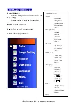
Page 8: ...mpany LLC www i techcompany com 7 Figure 2 Remove screws Step 3 Figure 3 take WKP series rackmount KVM slide in rack mount bracket Step 4 Figure 4 screw in hold WKP series rackmount KVM in left right...

Page 9: ...or off the main board AUTO auto setting all funtions LCD OSD Funtions 1 Color a Contrast b Brightness c Color Adjust d Color Temp e Back 2 Image Setting a Clock b Phase c Gamma d Sharpness e Back 3 Po...

Page 10: ...en tap down side of touchpad then move finger 1 Finger Left Button It s same as the left button of mouse And it could be setup as the function as selected for example Click Select Content Menu Run etc...

Page 11: ...nd set password for each computer 2 Features Use One KVM Console to control 8 16 PCs Automatic KVM signal simulation able to boot up PC simultaneously Support advanced function of Logitech and Microso...

Page 12: ...rd and video connecter 4 During installation or operation if you face any signal problem you can press Scroll Lock Scroll Lock R to reset from the keyboard The keyboard led and front panel LEDs will b...

Page 13: ...r 8 16 computers After you activate hot key function the OSD menu will show on the screen and then followed by typing the channel number to switch If you connected additional tier of switches you shou...

Page 14: ...ock twice as the initial hot key and followed by channel number to switch over different computers 2 On Screen Display Operation A You may start with two Scroll Lock keystrokes to activate OSD On Scre...

Page 15: ...and it can be different in each channel c For the channel without setting the password for general users it will be required to input the Administrator password d By skipping the setup of Administrat...

Page 16: ...lity 3 in 1 KVM cable for optimum operation 3 To prevent potential power damage please don t use 2 wire extension cord and ensure AC outlets at PCs and monitors are on the same phase and have correct...

Page 17: ...Hot Plug please make sure your O S and mouse software driver supports the Hot Plug function Troubleshooting 1 Ensure that all cables are well seated Label all of cables with the number for each respec...

Page 18: ...wer switch is off but the switch still works fine or power adapter is unplugged from the switch but the switch still works fine KVM Switch unit draws the power source from power adapter and all PC s P...

Page 19: ...C Rules Operation is subject to the following two conditions 1 This device may not cause harmful interference 2 This device must accept any interference received Including interference that may cause...

Reviews: