i
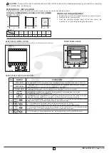
ELECTRICAL INSTALLATION
The electrical connection diagram is shown on the controller enclosure as below.
1
2
3
4
5
6
10
11 12 13 14 15 16 17 18
7
8
9
NO
NC
CM
RELAY1
SSR1
NO
NC
CM
RELAY2
SSR2
SUPPLY
L
N
AI - 5982
MECHANICAL INSTALLATION
The label on the controller identifies the serial number, wiring connections and batch number.
CAUTION:
To prevent the risk of electrical shock, switch off the power before making/removing any connection or removing
the controller from its enclosure.
INSTALLATION GUIDELINES
1. Prepare the cut-out with proper dimension as shown in figure.
2. Remove clamp from controller.
3. Push the controller through panel cut-out and secure the
controller in its place by tightening the side clamp.
OVER ALL DIMENSIONS & PANEL CUT OUT (IN MM)
MODEL:- AI - 5982
A
B
D
E
G
F
PANEL
CUTOUT
TABLE : 1
Model
Dim
96
96
10
45
92
92
9
A
B
H
C
D
F
G
E
89
AI-5982
FRONT PANEL LAYOUT
AI - 5982
1
4
5
7
2
3
OP1
OP2
SOAK
PV
SV
SET
RESET
START
-therm
i
AI-5982
6
FRONT PANEL LAYOUT DESCRIPTION :
Sr.
NAME
FUNCTION
Glows when OP1 is ON & flashes when delay time (dly1) is in operation(if selected mode is ON-OFF)
1
OP1 LED
Glows when Soak mode is selected & flashes when Soak timer is in operation.
OP2 LED
SOAK LED
(
(
(
along with UP key. (4) To scroll the parameter & to store its value.
1) For SP programming. 2) To access Control mode. 3) To access Configuration mode
(
(
(with SET key) . (3) To acknowledge Alarm. (4) To Reset the SOAK timer
1) To increase/alter parameter value in program mode. 2) To Enter in configuration mode
(
(
1) To decrease / alter parameter value in program mode. 2) To start Soak timer.
It will display (1) Measured value of selected input or Error massages in run mode.
(2) Parameters Value in program mode.
It will display (1) SP (Main set point) / SP2 (Auxiliary/Alarm) set value / Set Soak time value/
balance or elapsed soak time in run mode. (2) Parameter code in program mode.
2
3
4
5
6
7
UPPER
DISPLAY
LOWER
DISPLAY
SET
KEY
SHIFT
KEY
UP
KEY
DOWN
KEY
(1) To increase/alter parameter value in program mode with Up / Dn Key.
(2) Press for 3Sec in Programming this will help to go back to previous parameter.
Glows when OP2 is ON & flashes when alarm condition persists even after acknowledged.
delay time (dly2) is in operation(if selected mode is ON-OFF).
or
2
OIM AI-5X82 V2.1 Page 2 of 6


