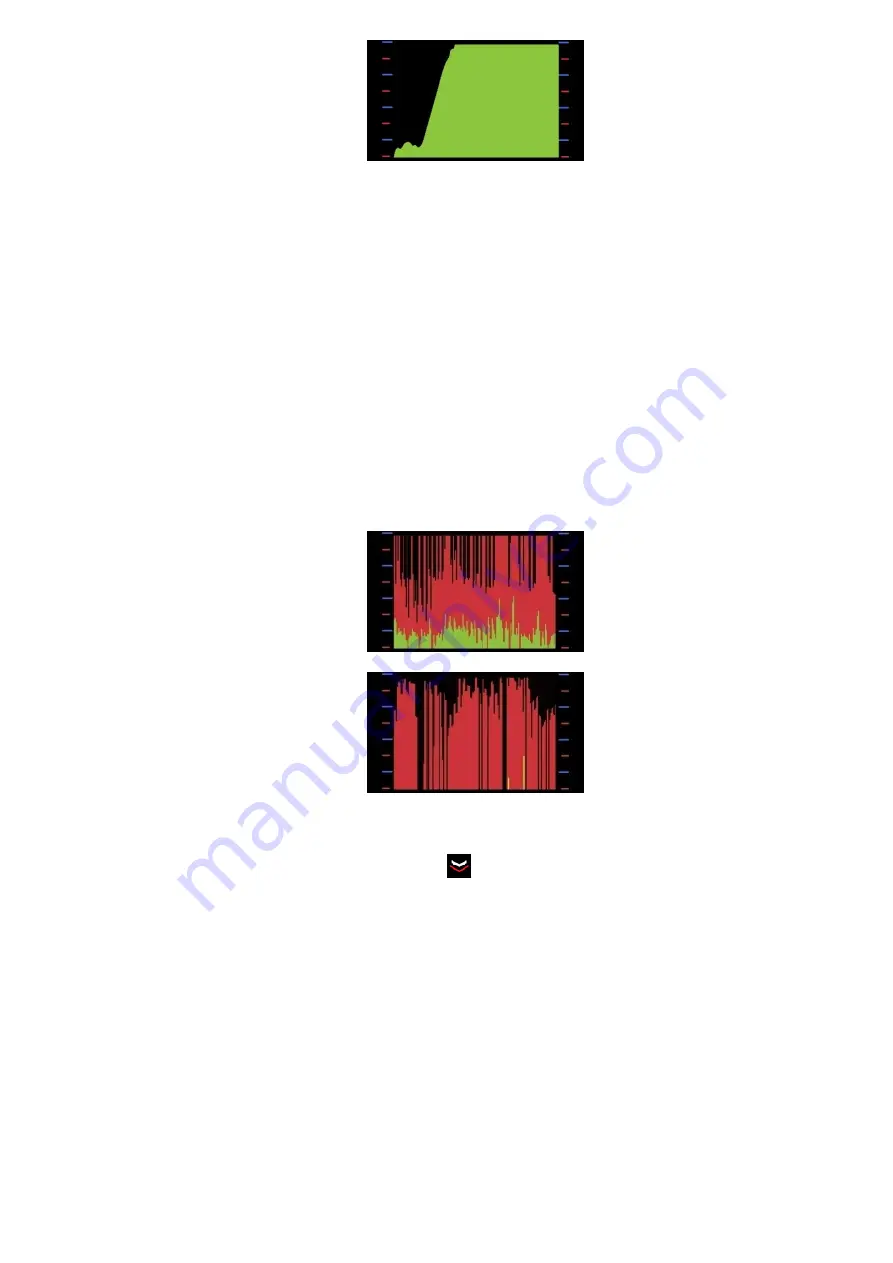
Fig.9 -
Signal strength level increasing when approaching an analog transmitter
-I
f the signal is periodic, the device will display its frequency in MHz.
-I
f there is a strong enough and permanent enough signal level all over the room, it may mean that there
is a powerful external source of radio transmission nearby (cell phone tower, strong Wi-Fi access points in
the next rooms, etc). In this case, try to switch on all device’s filters
, as this will significantly reduce the in-
terference of such sources on the search process.
-U
se the sound indication mode when searching.
In most cases, the demodulated sound produced by the
device is very informative (in the immediate vicinity of radio microphone, the nature of the sound changes
significantly - it completely goes off, or, conversely, sounds can be clearly noticeable; GSM / GPRS trans-
mitter can be easily identified by the characteristic "cod", Wi-Fi / Bluetooth transmitters - by "rustling" or
frequent "knocking"). Earphones are recommended for acoustic control.
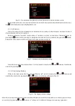
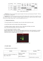
-I
f there are spikes and valleys, in addition to the spaces on the green graph of average values
as shown
in Fig.10,
then there is a high probability of an operating digital transmitter
.
The digital character of the de-
tected signal is also defined by obvious transmission/pause intervals on the peak values graph and the higher
amplitude of peak values, compared to the average ones, as shown in Fig
.10.
а) 2G/3G transmitter signal during talktime
b) Wi-Fi signal of equipment
Fig. 10 – Graphs in the coverage area of digital transmitters
In this case, decrease sensitivity by pressing the
button to the level where the red graph of peak val-
ues doesn’t "go into overdrive"
.
Continue your search while considering the peak values graph
.
Repeat the search, using measurement channel ANT2 to identify devices working at frequency 2.4 GHz
and above, such as Wi-Fi/Bluetooth transmitters of 2.4/5 GHz, analog cameras 2.4/5.8 GHz, etc. Paying at-
tention to the constant component of the Wi-Fi signal and Bluetooth devices, as a rule, is weak. Instead, a
search should be made focusing on the peak values of the signal (red graph).
2.3.2.3 "Oscilloscope" mode
2.3.2.3.1 Graphic presentation of information in the "Oscilloscope" mode
"Oscilloscope" mode is an auxiliary Product’s operating mode intended for displaying radio signal oscil-
lograms. The Product’s screen in this mode is shown in Fig.11.


