—
45
—
AP-
16
00T-
PMCL
1
Shield the camera sensor.
If a lens is attached, use the lens cap as a shield, for example.
2
Configure the threshold level for defective pixel detection.
Up to 200 pixels can be corrected for each of the three sensors.
The threshold value is specified as a percentage.
The default setting is "10" with 10% of the full scale (100%) specified as the threshold
value.
3
Execute [BlemishDetect] to start automatic detection.
After detection, the interpolation data is saved to the camera's internal memory.
To check the number of interpolated pixels after automatic detection
You can check the number of pixels interpolated via automatic detection by loading the
BlemishNum data.
■
Manual configuration
1
Select the index in [BlemishCompensationIndex].
You can select from 1 to 200. However, configure the indexes in order starting with the smallest
index. If you skip indexes while configuring settings, interpolation may not be performed.
2
Specify the pixel points for interpolation using the
[BlemishCompensationPositionX] and [BlemishCompensationPositionY] settings.
You can configure values that are within the total effective pixel area. Specify pixels for which
interpolation is not necessary as -1. If 0 is specified, the first line or first pixel will be interpolated.
Note
BlemishCompensationDataClear[specify sensor][BlemishCompensationIndex], you can return a
specific pixel correction setting to the default value (storage not required).
3
Execute [BlemishStore].
Blemish compensation data will be stored.
4
Set [BlemishEnable] to [True], and execute interpolation.
If it is set to [False] , Blemish compensation is not effective.
ShadingCorrection
The ShadingCorrection function corrects non-uniformity (i.e., shading) in the amount of light
generated by the lens and lighting equipment. Using this function allows correction even if top,
bottom, left, and right shading is not symmetrical in relation to the center of the screen (H, V).
This function can be used even when the effective image area is limited (an area with both
Width and Height set to more than 128 must must be configured) by the ROI function. In
such cases, the correction area is included in the image area configured by the ROI.
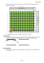
For a full image, the number of correction blocks is 12 (H) × 9 (V) blocks and calculation
errors in the correction data are minimized due to the small interpolation areas. Each block is
128 × 128 pixels. The total size of the blocks is 1536 (H) × 1152 (V), but the actual number
of effective pixels for the camera is 1456 (H) × 1088 (V). The ineffective peripheral areas
will be deleted internally on the camera automatically.

