98
9. CC-Link
operation
case
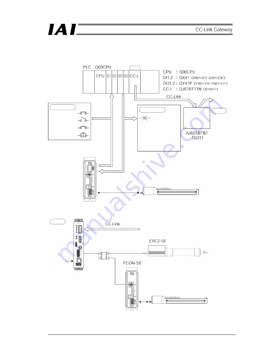
9.1 Outline
of
configuration
(Mitsubishi)
Station No. 0
Power
Switch
Operation
Pause
Emergency stop
release
Emergency stop
Positioning completed
Operation preparation
completed
Servo on
Operation
Alarm
Pause
Emergency stop
release
Indication lamp
Remote I/O
Input 8 points
Output 8 points
PCON-CY controller
Gateway unit
Station No. 5
RCP2 actuator
First axis
Second axis
(Link axis 0)
Gateway unit
Station No. 1
Personal
computer or
teaching box
SIO link
Third axis
(Link axis 1)
RCP2 actuator
Summary of Contents for CC-Link
Page 1: ...IAI America Inc CC Link RCM GW CC Gateway Unit Operation ManualFirst Edition ...
Page 4: ......
Page 10: ...6 1 5 How to identify model RCM GW CC Basic model For CC Link Gateway unit ...
Page 12: ...8 2 2 External dimension drawing Mounting dimension ...
Page 78: ...74 ...
Page 82: ...78 Position data measurement value Present position 1 2 3 4 4 5 6 7 ...
Page 84: ...80 Speed acceleration and deceleration set value Actuator speed Speed n2 Speed n3 1 2 3 ...
Page 88: ...84 Command position No Completion position No 1 2 3 4 5 6 ...
Page 91: ...87 ...
Page 93: ...89 ...
Page 125: ...121 No 3 Axis 1 pause No 3 Axis 1 pause lamp No 3 Axis 1 STP ...
Page 130: ...126 ...
Page 131: ......


