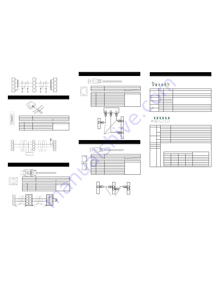
CompoNet Type
Refer to the instruction manuals for Field Network master unit and mounted PLC for the details.
Connector Name
CompoNet Connector
Cable Side
Prepare a connector complied with CompoNet standards.
Controller Side
XW7D-PB4-R
Produced by OMRON
Pin No.
Signal Name
Description
Applicable cable diameter
1 BS+
(RD)
Communication Power
(Note 1)
2
BDH (WT)
Signal line H side
3
BDL (BL)
Signal line L side
4 BS-
(BK)
Communication Power Supply -
(Note 1)
CompoNet Dedicated Cable
Note 1 It is not necessary to supply the communication power. (Internal power source is
used.)
If conducting multi power supply to other slave devices via communication
cables, there is no problem with connecting the power supply to BS+ and BS-
terminals.
MECHATROLINK Type
Refer to the instruction manuals for Field Network master unit and mounted PLC for the details.
Connector Name
MECHATROLINK
Cable Side
Prepare a connector complied with MECHATROLINK standards.
Controller Side
DUSB-ARB82-T11A-FA
Produced by DDK
Pin No.
Signal Name
Description
Applicable cable diameter
A1/B1 NC
Disconnected
A2/B2 /DATA
Signal line - side
A3/B3 DATA
Signal line + side
A4/B4 SH
Shield
MECHATROLINK
Dedicated Cable
EtherNet/IP Type
Refer to the instruction manuals for Field Network master unit and mounted PLC for the details.
Connector Name
EtherNet/IP Connector
Cable Side
8P8C Modular Plug
Controller Side
8P8C Modular Jack
Pin No.
Signal Name
Description
Applicable cable diameter
1
TD+
Data s
2
TD-
Data sending -
3
RD+
Data rec
4 –
Disconnected
5 –
Disconnected
6
RD-
Data receiving -
7 –
Disconnected
8 –
Disconnected
For EtherNet cable, use a
straight STP cable that
possesses the performance of
Category 5e or more.
EtherCAT Type
Refer to the instruction manuals for Field Network master unit and mounted PLC for the details.
Connector Name
EtherCAT Connector
Cable Side
8P8C Modular Plug
Controller Side
8P8C Modular Jack
Pin No.
Signal Name
Description
Applicable cable diameter
1
TD+
Data s
2
TD-
Data sending -
3
RD+
Data rec
4 –
Disconnected
5 –
Disconnected
6
RD-
Data receiving -
7 –
Disconnected
8 –
Disconnected
For EtherNet cable, use a
straight STP cable that
possesses the performance of
Category 5e or more.
Status LED
In this product, there are some LEDs mounted to show the status of the gateway and axes.
Shown below explains the layout of the LEDs and the patterns of lighting.
●
Gateway Status LEDs
○
Illuminating, × OFF
Name Color
Lamp
condition
Information
GN
○
Turned ON when system is ready (after power is turned ON and
CPU operating in normal condition)
RDY
/ALM
OR
○
Alarm
generated
EMG
RD
○
Emergency
stop
GN –
STATUS0
/NS/ERR
OR –
GN –
STATUS1
/MS/RUN
OR –
Condition differs depending on field network
[Refer to ERC3 Gateway Unit Instruction Manual for the details.]
OR
×
Internal bus communication with controller in normal condition
T.ERR
OR
○
Internal bus communication with controller in error
OR
×
Field network communication in normal condition
C.ERR
OR
○
Field network communication in error
●
Each axis status LEDs
○
Illuminating, × OFF,
☆
Flashing
Name Color
Lamp
condition
Information
○
Servo ON Status
☆
Servo-motor
Auto
OFF
condition
GN
×
Servo OFF Status
○
Alarm generated, Emergency stop
SYS
RD
× Normal
○
Absolute reset complete
GN
×
Absolute Function not to be used
○
Absolute reset incomplete
ABS
RD
×
Absolute Function not to be used
ST3 GN
ST2 GN
ST1 GN
ST0 GN
Status display
(i) The current command current ratio (percentage to the rating) is displayed when
servo is ON.
(ii) Simple alarm code is displayed when an alarm is issued.
[Refer to ERC3 Gateway Unit Instruction Manual for the details.]
○
Illuminating, × OFF
ST
3 2 1 0
Command Current Ratio
ALM8 ALM4 ALM2 ALM1 Simple
alarm
code
× × × × 0.00%
to
6.24%
× × ×
○
6.25%
to
24.99%
× ×
○
○
25.00%
to
49.99%
×
○
○
○
50.00%
to
74.99%
○
○
○
○
75.00% to100.00% or more
BK (BS-)
BL (BDL)
RD (BS+)
WT (BDH)
Front View of
Connector on
Controller side
1
2
3
4
Front View of
Connector on
Controller side
B1
A1
A4
B4
1
8
Front View of
Connector on
Controller side
8
1
8
1
Front View of
Connector on
Controller side
Master Unit
Switching Hub
Slave Devices
EtherNet Straight Cable, Category 5e or more
Double shielded cable braided with aluminum foil
recommended
ERC3 Gateway Unit
EtherNet/IP Type
Master Unit
Slave Devices
EtherNet Straight Cable
Category 5e or more
Double shielded cable braided with aluminum
foil recommended
(Note) Terminal resistance is not required
ERC3 Gateway Unit
EtherCAT Type
AX*: AX0 = 1
st
Axis to AX3 = 4
th
Axis
BS+
BDL
BDH
BS-
BS+
BDL
BDH
BS-
BS+
BDL
BDH
BS-
Master Unit
Slave Devices
Terminal
Resistance
121
Ω
ERC3 Gateway
CompoNet Type
Connect the terminal
resistor if the unit is
placed at the end of
the network.
24V
Power Supply
Supply power separately to the slave devices
that requires the communication power supply.
It is not necessary to supply communication power
to ERC3 Gateway Unit, however, there is no problem
even if communication power is supplied.
4
3
2
1
4
3
2
1
4
3
2
1
A4
A3
A2
A1
B4
B3
B2
B1
Master Unit
Slave Devices
MECHATROLINK
Cable
MECHATROLINK Cable
ERC3 Gateway
MECHATROLINK Type
Terminal Resistance
JEPMC-W6022
Connect the terminal resistor
if the unit is placed at the end
of the network.
130
Ω
SH
DATA
/DATA
NC
Connect shield to
connector shell
Connect shield to
connector shell
SH
DATA
/DATA
NC
SH
DATA
/DATA
NC
ERC3 Gateway
PROFIBUS Type
Slave Devices
Master Unit
Terminal Resistance is required
to be mounted on the terminal.
Grounding resistance at 100
Ω
or less
+5V
A-Line
B-Line
GND
+5V
A-Line
B-Line
GND
+5V
A-Line
B-Line
GND
390
Ω
390
Ω
220
Ω
390
Ω
390
Ω
220
Ω


