13. How to Reset an
Absolute Encoder
234
(6) Press the EMERGENCY STOP switch.
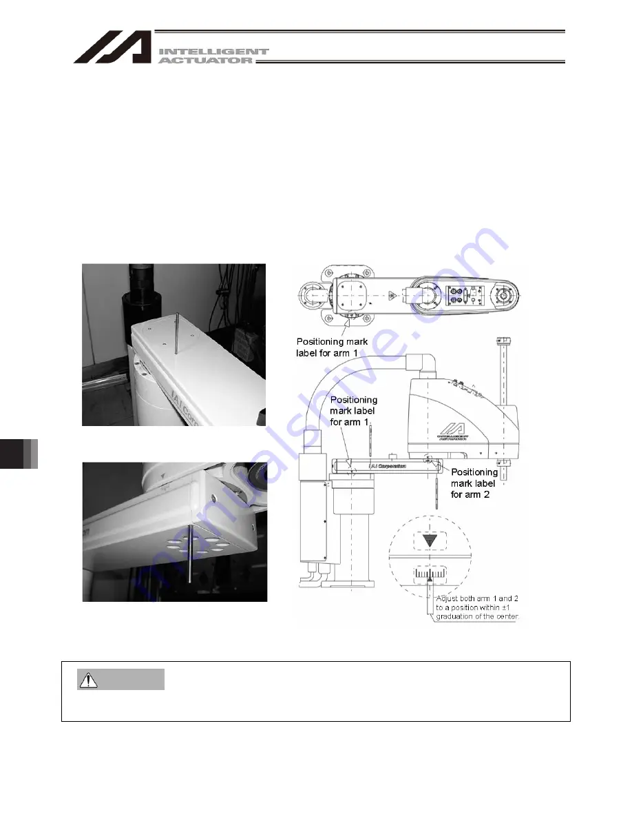
(7) When performing an absolute reset for arm 1, set an adjustment jig (pin) in arm 1 to fix the arm at the
reference position. When performing an absolute reset for arm 2, set an adjustment jig (pin) in arm 2 to fix
the arm at the reference position.
Set the jig after confirming that the EMERGENCY STOP switch is pressed.
Set the jig after adjusting the arm to the reference position, using the positioning mark label as a guide.
Only arm 1 has a cover, which is fixed with setscrews. Remove the setscrews and remove the cover
before setting the jigs.
It is recommended that an adjustment jig is used to perform an absolute reset. With arm 1 or 2, however,
rotation data can be reset as long as positioning preciseness of “center of positioning mark label ±1
graduation” is ensured.
To perform an absolute reset for arm 2 with an arm length of 120, turn the arm at a right angle and set the
jig as shown in the reference position drawing in Fig. 13.17.
Arm 1
(Arm length 500/600, 700/800)
Arm 2
(Arm length 500/600, 700/800) Fig. 13.23 Arm length 500/600, 700/800 Reference Position
Always press the EMERGENCY STOP switch before setting an adjustment jig. Failure to do so may
cause the actuator to malfunction and result in a serious accident.
Warning
Summary of Contents for IA-101-TT-USB
Page 2: ......
Page 4: ......
Page 8: ......
Page 50: ...1 Before You Begin 42 1 4 Connection to Controller Fig 1 48 X SEL K J Type Controller ...
Page 52: ...1 Before You Begin 44 Figure shows example of TT Fig 1 50 Table Top Actuator TT TTA ...
Page 53: ...1 Before You Begin 45 Fig 1 51 X SEL KX JX Type Controller ...
Page 62: ...1 Before You Begin 54 Fig 1 60 ASEL Type Controller USB Cable ...
Page 63: ...1 Before You Begin 55 Fig 1 61 PSEL Type Controller USB Cable ...
Page 189: ...9 Symbol Edit Window 181 ...
Page 251: ...13 How to Reset an Absolute Encoder 243 Fig 13 38 Arm Length 120 Reference Position ...
Page 386: ...16 Appendix 378 ...
Page 391: ......


