4. Program Edit W
indow
118
[2] Displaying Cycle Time Measurement Result
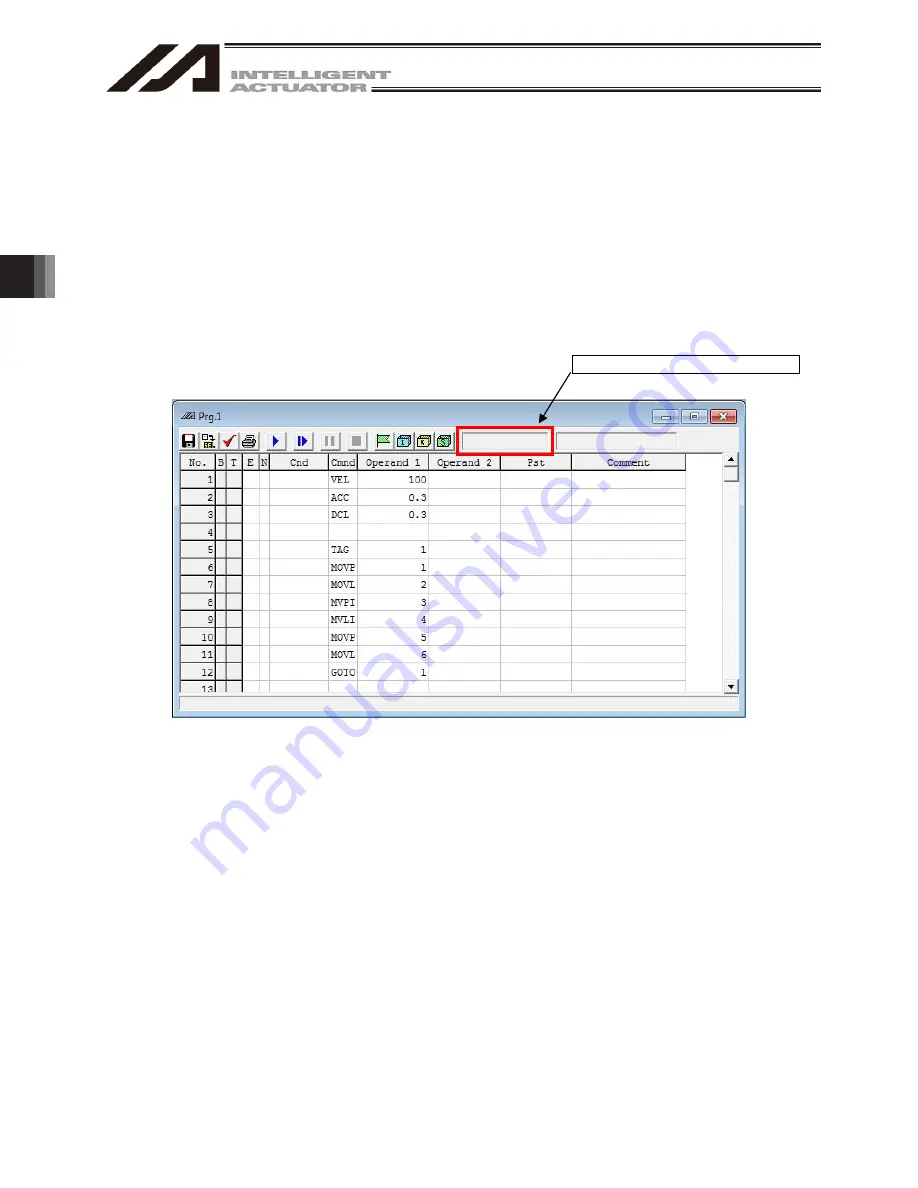
Once a program gets operated, cycle time will be measured and the result will be displayed at the
position marked in red.
Once the program starts executed and the step with “S” being shown gets executed, measurement
will start and display shows -----.---s.
Once the step with “E” being shown is completed, the measurement will finish and the cycle time
measurement result will be displayed.
The time to be shown should be from 0.000sec to 86399.999sec (one day).
Once the first measurement is completed and the step with “S” being shown has been executed,
measurement will start again and -----.---s will be displayed.
If a change is made to the cycle time measurement area section after measurement is finished, the
display will turn to blank.
Fig. 4. 34 Measurement Result Display
Blank
: Status of Cycle Time Measurement Not Executed
-----.--- Displayed : Status of Cycle Time Measurement Under Execution
Time Displayed : Status of Cycle Time Measurement Completed
Measurement Result Display Area
Summary of Contents for IA-101-X-MW
Page 2: ......
Page 4: ......
Page 8: ......
Page 50: ...1 Before You Begin 42 1 4 Connection to Controller Fig 1 48 X SEL K J Type Controller...
Page 52: ...1 Before You Begin 44 Figure shows example of TT Fig 1 50 Table Top Actuator TT TTA...
Page 53: ...1 Before You Begin 45 Fig 1 51 X SEL KX JX Type Controller...
Page 62: ...1 Before You Begin 54 Fig 1 60 ASEL Type Controller USB Cable...
Page 63: ...1 Before You Begin 55 Fig 1 61 PSEL Type Controller USB Cable...
Page 189: ...9 Symbol Edit Window 181...
Page 251: ...13 How to Reset an Absolute Encoder 243 Fig 13 38 Arm Length 120 Reference Position...
Page 386: ...16 Appendix 378...
Page 391: ......


