6. Position Data Edit W
indow
131
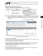
Axis 1 to 4
Specify each desired position for Axis 1 to Axis 4. In the case of the JX/KX, PX/QX, RX/SX,
RXD/SXD, RAX/SAX, RAXD/SAXD, and MSEL-PCX/PGX controllers, specify a desired position
for each SCARA axis. The setting range is from –99999.999 to 99999.999.
Axis 5, 6
Specify a desired position for Axis 5 and Axis 6. The setting range is from -99999.999 to 99999.99.
Axis 5 to 8
Specify each desired position for Axis 5 to Axis 8.
In the case of the RXD/SXD and RAXD/SAXD controller, specify a desired position for each SCARA
axis.
The setting range is from -99999.999 to 99999.999.
Arm 1 to Arm 4, Arm 5 to Arm 8
Specify each desired target arm system for SCARA axes (Axis 1 to Axis 4) and SCARA axes (Axis
5 to Axis 8) as either “Left” or “Right.”
(Note) The specification of each target arm system specified by this item is valid with respect to
the following operations:
• Move using the “Move” button ( ) or “Continuous Move” button ( ) on the Edit
Position screen. (If no PTP target arm system is set as part of the position data, the
specified operation is performed by assuming the “current arm system (movement of
the opposite arm system permitted if the current arm system cannot be moved).”)
• Servo operation SEL command that uses the position data
(Note) When editing, each arm system can be specified by entering the first letter of the pattern to
be specified:
[Example] • Enter “L”
Left
• Enter “R”
Right
(Note) Arm 1 to Arm 4 are displayed only on the X-SEL-RX/SX, RXD/SXD, RAX/SAX and
MSEL-PCX/PGX controllers.
(Note) Arm 5 to Arm 6 are displayed only when the X-SEL-RXD/SXD and RAXD/SAXD controller
is used and SCARA axes (axes 5 to 8) are connected.
Vel
Specify a desired speed.
Available range is from 1 to 9999.
However, for X-SEL-J/K, P/Q, R/S, RA/SA, SSEL, PSEL, TT and TTA, from 1 to All Axes Common
Parameter No. 21”Operation Speed at Max for Input Check” is the setting range when All Axes
Common Parameter No. 20 “Maximum Operation Speed Check” is set to 0.
Acc
Specify a desired acceleration.
Available range is from 1 to 9.99.
However, 1 to 4 axes for X-SEL-PX/QX bigger one between from 0.01 to All Axis Common
Parameter No. 22 “SCARA Axis CP Acceleration Maximum” and Parameter No. 203 “Linear Axis
Acceleration Maximum” is the setting range.
For when All Axes Common Parameter No. 18 “Maximum Operation Acceleration/Deceleration
Check Timing” is set to 0 for X-SEL-P/Q, R/S, RA/SA and SSEL, or for X-SEL-J/K, JX/KX, ASEL,
TT and TTA, setting value in All Axes Common Parameter No. 22 “Acceleration Maximum” and
“CP Acceleration Maximum” is the maximum value.
Summary of Contents for IA-101-X-MW
Page 2: ......
Page 4: ......
Page 8: ......
Page 50: ...1 Before You Begin 42 1 4 Connection to Controller Fig 1 48 X SEL K J Type Controller...
Page 52: ...1 Before You Begin 44 Figure shows example of TT Fig 1 50 Table Top Actuator TT TTA...
Page 53: ...1 Before You Begin 45 Fig 1 51 X SEL KX JX Type Controller...
Page 62: ...1 Before You Begin 54 Fig 1 60 ASEL Type Controller USB Cable...
Page 63: ...1 Before You Begin 55 Fig 1 61 PSEL Type Controller USB Cable...
Page 189: ...9 Symbol Edit Window 181...
Page 251: ...13 How to Reset an Absolute Encoder 243 Fig 13 38 Arm Length 120 Reference Position...
Page 386: ...16 Appendix 378...
Page 391: ......


