6. Position Data Edit W
indow
143
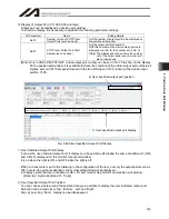
Display of Output Port (V11.00.00.00 and later)
Output port can be displayed on position edit window.
To show the display, it is necessary to establish the following parameter settings.
I/O Parameter
Name
Setting Details
No.74
Number of Use of PC/TP User
Output Ports (such as hand)
Set the number of output ports to be displayed on
the position edit window.
No.75
PC/TP User Output Port Start
Number (such as hand)
Set the output port start number.
With this number as the start number, ports are
displayed in a row for the number set in No. 74.
(Note) The display will not be shown if a number
out of the output ports is set. An error will
also not be shown.
(Note)
Only in XSEL-P/Q/PCT/QCT, virtual output port number can be set in No. 75 to show on the display.
On the position edit window, it is available to check the condition of the virtual output ports of the pick
& place axis on CT4 that opens/closes with the turn-ON (open) / OFF (close) of the virtual output
port No. 7305.
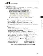
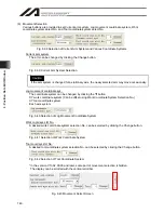
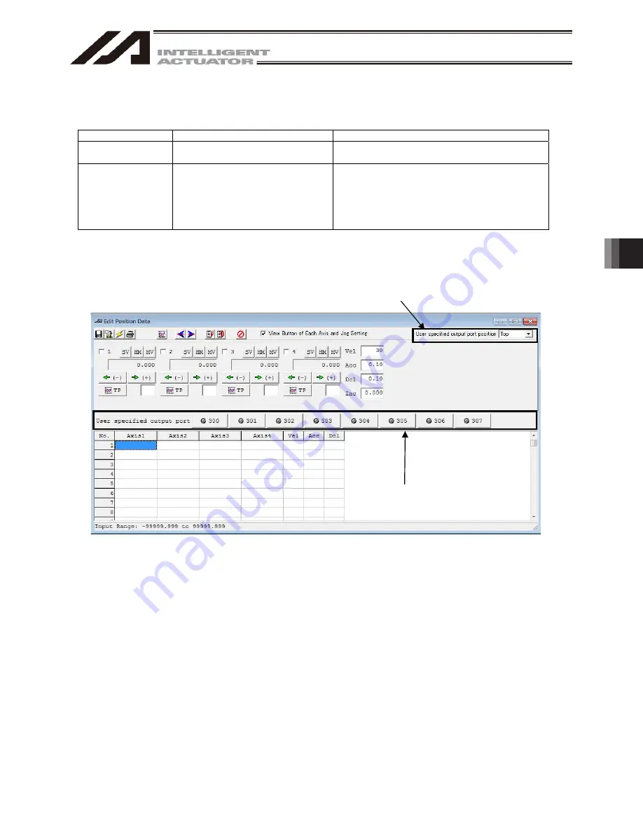
Fig. 6.46 User Specified Output Port Display
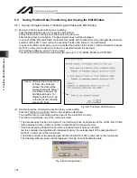
1) User Indicated Output Port Display
It shows the user indicated output port. It displays on the position edit window the same condition as 1 (ON)
and 0 (OFF) displayed on the monitor output port window.
It is on when the light is ON, and OFF when the light is off.
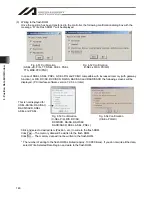
When a check mark is put to the following in the configuration of the tool, not only the output ports such as
300, but also the symbols defined in the symbol edit window will be displayed.
●
Display symbol names to variable monitor, I/O port monitor, flag monitor and position edit window
[Refer to 9. Symbol Edit and 15. Tools]
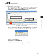
2) User Specified Output Port Position
You can choose where around the position data you would like to display the user indicated output port.
Selection can be made from ‘Top’, ‘Bottom’, ‘Left’ and ‘Right’.
Also, by selecting “None”, display can be disappeared.
2) User specified output port position
1) User specified output port display
Summary of Contents for IA-101-X-MW
Page 2: ......
Page 4: ......
Page 8: ......
Page 50: ...1 Before You Begin 42 1 4 Connection to Controller Fig 1 48 X SEL K J Type Controller...
Page 52: ...1 Before You Begin 44 Figure shows example of TT Fig 1 50 Table Top Actuator TT TTA...
Page 53: ...1 Before You Begin 45 Fig 1 51 X SEL KX JX Type Controller...
Page 62: ...1 Before You Begin 54 Fig 1 60 ASEL Type Controller USB Cable...
Page 63: ...1 Before You Begin 55 Fig 1 61 PSEL Type Controller USB Cable...
Page 189: ...9 Symbol Edit Window 181...
Page 251: ...13 How to Reset an Absolute Encoder 243 Fig 13 38 Arm Length 120 Reference Position...
Page 386: ...16 Appendix 378...
Page 391: ......


