


10. Coordinate System Definition Data Edit W
indow
194
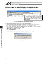
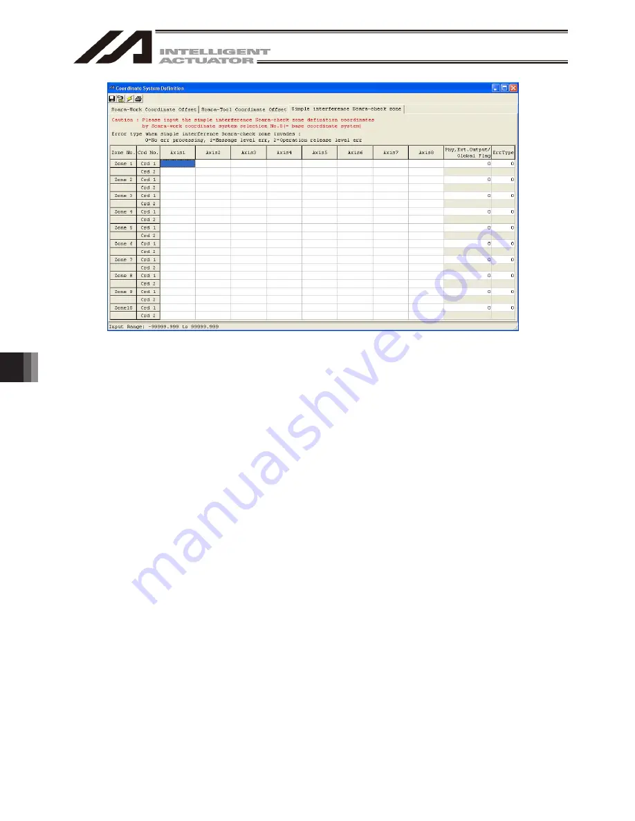
Fig. 10.16 Simple Interference Check Zone Definition Coordinates Setting Screen
(X-SEL-RXD/SXD, RAXD/SAXD)
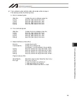
Zone No.:
Indicates the zone number.
Coordinate No.: Indicates the coordinate number. Coordinate 1 and Coordinate 2 are available.
Physical/Expansion Output Port No./Global Flag No.:
Select a desired output number to be output when the axis enters the check zone.
(In the case of the X-SEL-RX/SX, RXD/SXD, RAX/SAX, RAXD/SAXD controller, an
expansion output port number can also be entered.)
Error Type:
Select a desired type of errors.
0 = Do not handle errors.
1 = Output message level errors.
2 = Output operation-cancellation level errors.
(For Axis 5 to Axis 8, this item is displayed only on the X-SEL/RXD/SXD, RAXD/SAXD
controller.)
(Note) Contact area data for two SCARA robots (Axis 1 to Axis 4, and Axis 5 to Axis 8) cannot be set for
one check zone.
Summary of Contents for IA-101-X-MW
Page 2: ......
Page 4: ......
Page 8: ......
Page 50: ...1 Before You Begin 42 1 4 Connection to Controller Fig 1 48 X SEL K J Type Controller...
Page 52: ...1 Before You Begin 44 Figure shows example of TT Fig 1 50 Table Top Actuator TT TTA...
Page 53: ...1 Before You Begin 45 Fig 1 51 X SEL KX JX Type Controller...
Page 62: ...1 Before You Begin 54 Fig 1 60 ASEL Type Controller USB Cable...
Page 63: ...1 Before You Begin 55 Fig 1 61 PSEL Type Controller USB Cable...
Page 189: ...9 Symbol Edit Window 181...
Page 251: ...13 How to Reset an Absolute Encoder 243 Fig 13 38 Arm Length 120 Reference Position...
Page 386: ...16 Appendix 378...
Page 391: ......


