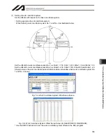
10. Coordinate System Definition Data Edit W
indow
195
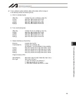
When simple interference check zone No. 1 is selected, entry of the tool into the rectangular solid will not
be detected if Rb is outside the 0 to 180°range. To enable detection regardless of the R-axis coordinate,
leave Coordinate 1 and Coordinate 2 in the R column in the Zone 1 line blank.
With simple interference check zone No. 2 and No. 3, where either the maximum or minimum coordinate
can be set to any value, enter a value outside the opening range for the maximum or minimum coordinate
(1000 in zone 2, 1000 or -1000 in zone 3).
The maximum/minimum coordinate can be set in either Coordinate 1 or Coordinate 2.
The simple interference check zones are set so that output port No. 311 turns ON when entry into simple
interference check zone No. 1 is detected, No. 312 turns ON when entry into simple interference check
zone No. 2 is detected, and port No. 313 turns ON when entry into simple interference check zone No. 3 is
detected.
If physical output numbers and global flag numbers are duplicated, chattering will occur and the result will
become unstable. Do not set overlapping numbers.
Use of the simple interference check zone function slows the CPU performance significantly. When the
function is not used, set 0 in “Phy. Output/Global Flag” and “Err Type” to disable the function.
* Use the DFIF instruction to set the simple interference check zones in the SEL program.
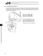
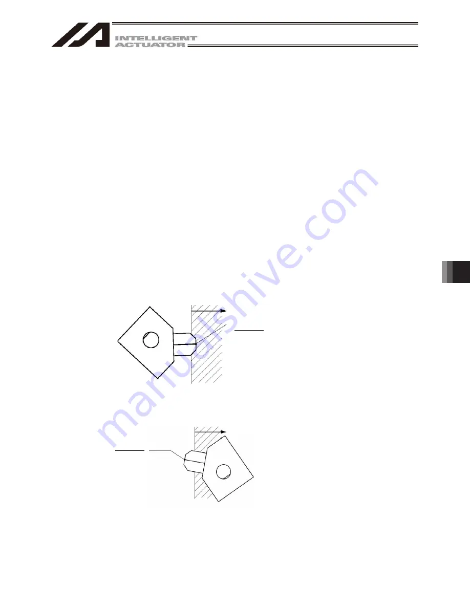
(3) Note on detection while a tool coordinate system is selected
While a tool coordinate system is selected, entry into the simple interference check zone is detected
based on the tool end, not the center of the installation surface.
Depending on the moving track, a part of the tool other than the end may enter the simple interference
check zone, as illustrated below. In this case, detection will not occur until the tool end enters the simple
interference check zone. Exercise due caution.
Simple interference check zone
Tool end
Tool end
Simple interference check zone
Summary of Contents for IA-101-X-MW
Page 2: ......
Page 4: ......
Page 8: ......
Page 50: ...1 Before You Begin 42 1 4 Connection to Controller Fig 1 48 X SEL K J Type Controller...
Page 52: ...1 Before You Begin 44 Figure shows example of TT Fig 1 50 Table Top Actuator TT TTA...
Page 53: ...1 Before You Begin 45 Fig 1 51 X SEL KX JX Type Controller...
Page 62: ...1 Before You Begin 54 Fig 1 60 ASEL Type Controller USB Cable...
Page 63: ...1 Before You Begin 55 Fig 1 61 PSEL Type Controller USB Cable...
Page 189: ...9 Symbol Edit Window 181...
Page 251: ...13 How to Reset an Absolute Encoder 243 Fig 13 38 Arm Length 120 Reference Position...
Page 386: ...16 Appendix 378...
Page 391: ......

