


11. Monitor
218
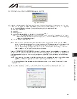
2) Set the I/O data to monitor
Fig. 11.35 I/O Monitor Setting
[IO Data Type] Select a type of I/O to monitor.
IN
: Input port and virtual input port
OUT
: Output port and virtual output port
IN/OUT : Virtual input and output port
(XSEL-RA/SA, RAX/SAX, RAXD/SAXD, TTA and MSEL-PCX/PGX only)
FLG
: Global flag (local flag not acceptable)
[Port No.]
Input a port number of I/O to monitor.
3) Select “PC Monitor Output” tab in Servo Monitor Screen.
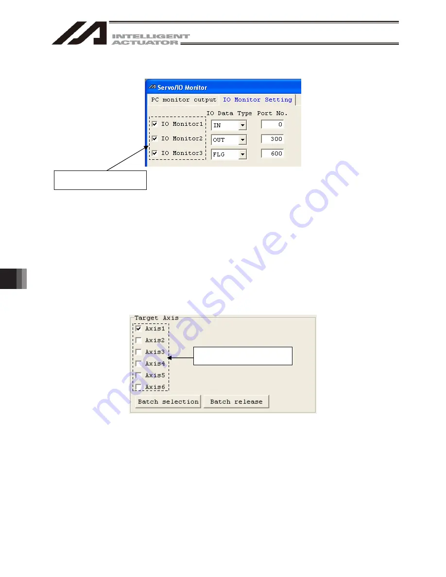
4) Select the applicable axis number for monitor data. It is unnecessary to set up when monitoring only I/O
data.
Fig. 11.36 Applicable Axis Number Select
Data with a check mark is
available for monitoring
Put a check mark on axis
numbers to monitor.
Summary of Contents for IA-101-X-MW
Page 2: ......
Page 4: ......
Page 8: ......
Page 50: ...1 Before You Begin 42 1 4 Connection to Controller Fig 1 48 X SEL K J Type Controller...
Page 52: ...1 Before You Begin 44 Figure shows example of TT Fig 1 50 Table Top Actuator TT TTA...
Page 53: ...1 Before You Begin 45 Fig 1 51 X SEL KX JX Type Controller...
Page 62: ...1 Before You Begin 54 Fig 1 60 ASEL Type Controller USB Cable...
Page 63: ...1 Before You Begin 55 Fig 1 61 PSEL Type Controller USB Cable...
Page 189: ...9 Symbol Edit Window 181...
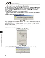
Page 251: ...13 How to Reset an Absolute Encoder 243 Fig 13 38 Arm Length 120 Reference Position...
Page 386: ...16 Appendix 378...
Page 391: ......


