13. How to Reset an
Absolute Encoder
270
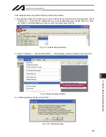
3) Adjust Arm 1, Arm 2 to the initial posture. The posture differs depending on the movement direction.
Click on “Display the explanation of initial posture” to check the explanations. Make to work on with the
emergency stop activated when moving the axes with hand. Click on the “OK” button after the work is
finished.
Fig. 13.91 Confirmation Window
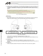
[Initial posture]
Arm1, Arm 2
Remove all the interferences of the peripheral devices, and set the posture to either of the left arm
system or the right arm system. It is set to right arm system when the unit is shipped out.
Arm 2 =
Negative direction of coordinate
Arm 1 =
Positive direction of coordinate
Arm 1 =
Negative direction of coordinate
Arm 2 =
Positive direction of coordinate
Fig. 13.92 Initial Posture
For the position, put it apart from the stopper position for 10deg or more.
Setting it too close to the stopper, Error No. B0D “Push Stopper Operation Start Position Error” may
occur at operation.
Initial posture of left arm system
Arm 1 = Positive direction of coordinate
Arm 2 = Negative direction of coordinate
Initial posture of right arm system (At the delivery)
Arm 1 = Negative direction of coordinate
Arm 2 = Positive direction of coordinate
Summary of Contents for IA-101-X-MW
Page 2: ......
Page 4: ......
Page 8: ......
Page 50: ...1 Before You Begin 42 1 4 Connection to Controller Fig 1 48 X SEL K J Type Controller...
Page 52: ...1 Before You Begin 44 Figure shows example of TT Fig 1 50 Table Top Actuator TT TTA...
Page 53: ...1 Before You Begin 45 Fig 1 51 X SEL KX JX Type Controller...
Page 62: ...1 Before You Begin 54 Fig 1 60 ASEL Type Controller USB Cable...
Page 63: ...1 Before You Begin 55 Fig 1 61 PSEL Type Controller USB Cable...
Page 189: ...9 Symbol Edit Window 181...
Page 251: ...13 How to Reset an Absolute Encoder 243 Fig 13 38 Arm Length 120 Reference Position...
Page 386: ...16 Appendix 378...
Page 391: ......


