13. How to Reset an
Absolute Encoder
332
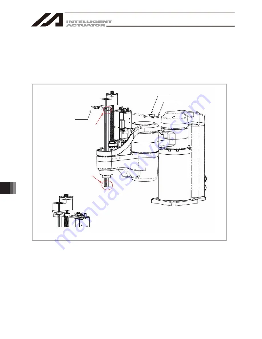
Attach the rotary axis pressing absolute reset tool for the four-axis type. (It is not necessary for the
three-axis type.)
Have the work during the emergency stop condition.
Regarding the R-axis absolute reset tool, take off the spline cover, apply Jig (A) to the flat on the spline shaft
and affix it to Jig (B) with screws. The position where Jig (A) is attached on the ball screw becomes the
home position of the R-axis. Pay attention to the orientation of the flat surface on the spline shaft.
[For how to detach and attach the spline cover, refer to 4.6 How to Inspect Visually on Timing Belt for
Vertical Axis and Rotary Axis in IXA SCARA Robot Instruction Manual (ME3776).]
Jig (B)
Jig (A)
D-cut Surface
D-cut Surface
2-M4 × 12
Jig Attached
Fig. 13.217 Figure for Attaching Absolute Reset Jig
Summary of Contents for IA-101-X-MW
Page 2: ......
Page 4: ......
Page 8: ......
Page 50: ...1 Before You Begin 42 1 4 Connection to Controller Fig 1 48 X SEL K J Type Controller...
Page 52: ...1 Before You Begin 44 Figure shows example of TT Fig 1 50 Table Top Actuator TT TTA...
Page 53: ...1 Before You Begin 45 Fig 1 51 X SEL KX JX Type Controller...
Page 62: ...1 Before You Begin 54 Fig 1 60 ASEL Type Controller USB Cable...
Page 63: ...1 Before You Begin 55 Fig 1 61 PSEL Type Controller USB Cable...
Page 189: ...9 Symbol Edit Window 181...
Page 251: ...13 How to Reset an Absolute Encoder 243 Fig 13 38 Arm Length 120 Reference Position...
Page 386: ...16 Appendix 378...
Page 391: ......


