1. Before
You Begin
57
1.5 Starting the Software (Online Connection)
[1] Turn off the power to the controller and PC, and connect the controller to the PC using the standard
RS232 cable or USB cable that comes with the software. Set the mode switch on the controller to the
MANU side.
When this software is started, the “safety velocity” mode is enabled (enable the safety velocity limit).
In this mode, in the case of orthogonal axis, the maximum velocity is limited to 250 mm/sec or below
in programs started from the PC software. In the case of SCARA axes, the maximum velocity during
CP operation is limited to 250 mm/sec or below (PTP operation: 3% or below). To operate programs
according to their programmed velocity commands, the safety velocity mode must be disabled.
Refer to 3.3, “Explanation of the Toolbar,” for how to enable/disable the safety velocity mode.
[2] Turn on the power to the controller and PC, and start Windows.
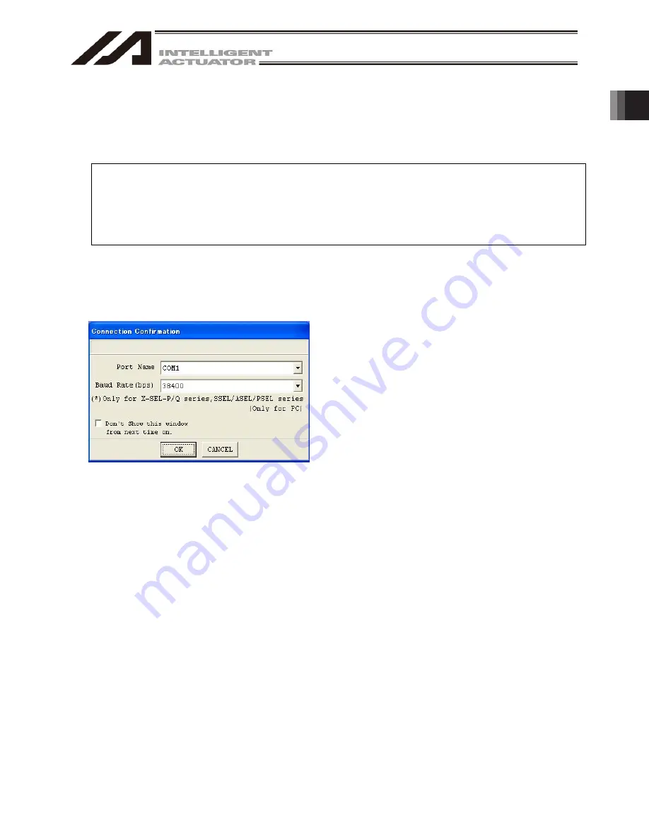
[3] Start this software. When the application is started, the Connection Confirmation window (Fig. 1.63) will
open first. In the list boxes of Port Name and Baud Rate (bps), select the communication port (*1) to which
the X-SEL, TT, TTA, SSEL, ASEL, PSEL, or MSEL controller is connected and an applicable baud rate
(*2),and then click OK.
(*1) Only the communication ports that are
available when the application is started can
be selected.
(*2) “57600” and “115200” bps are supported only
by the X-SEL-P/Q, PX/QX, R/S, RX/SX,
RXD/SXD, RA/SA, RAX/SAX, RAXD/SAXD,
TTA, SSEL, ASEL, PSEL, and MSEL
controllers.
(*3) “230400” bps is applicable only for
X-SEL-RA/SA, RAX/SAX, RAXD/SAXD.
Fig. 1.63 Connection Confirmation Screen
Summary of Contents for IA-101-X-MW
Page 2: ......
Page 4: ......
Page 8: ......
Page 50: ...1 Before You Begin 42 1 4 Connection to Controller Fig 1 48 X SEL K J Type Controller...
Page 52: ...1 Before You Begin 44 Figure shows example of TT Fig 1 50 Table Top Actuator TT TTA...
Page 53: ...1 Before You Begin 45 Fig 1 51 X SEL KX JX Type Controller...
Page 62: ...1 Before You Begin 54 Fig 1 60 ASEL Type Controller USB Cable...
Page 63: ...1 Before You Begin 55 Fig 1 61 PSEL Type Controller USB Cable...
Page 189: ...9 Symbol Edit Window 181...
Page 251: ...13 How to Reset an Absolute Encoder 243 Fig 13 38 Arm Length 120 Reference Position...
Page 386: ...16 Appendix 378...
Page 391: ......


