3. Menu W
indow
89
(10) Controller (C) [7] All Data Backup (X) ▪ Transfer to Controller/Divide File (L) (continued)
• Divide Files
Divide all the saved backup data (all data including program and position)
into program, position, parameter, symbol, X-SEL-JX/KX, PX/QX,
RX/SX/RXD/SXD,RAX/SAX/RAXD/SAXD and MSEL-PCX/PGX axis data.
Click Divide Files on the Transfer/Divide data screen.
The program, position, parameter symbol and controllers with the
coordinate system definition data are displayed in order on the File Save
Screen. Save them with a file name.
[8] Positioner Mode
This mode can be used when the SSEL, ASEL, or PSEL controller is under
the manual mode and positioner mode.
Start
Start the positioner mode.
Stop
Stop the positioner mode.
(Note) You can not change the parameters or write to flash ROM while the SSEL, ASEL, or PSEL
controller is under the positioner mode.
Perform this operation to stop the positioner mode before changing the parameters or
writing to flash ROM.
Acquire Positioner Mode Information
Acquire maintenance information (system data) in the positioner mode.
This item is displayed for SSEL, ASEL, and PSEL controllers.
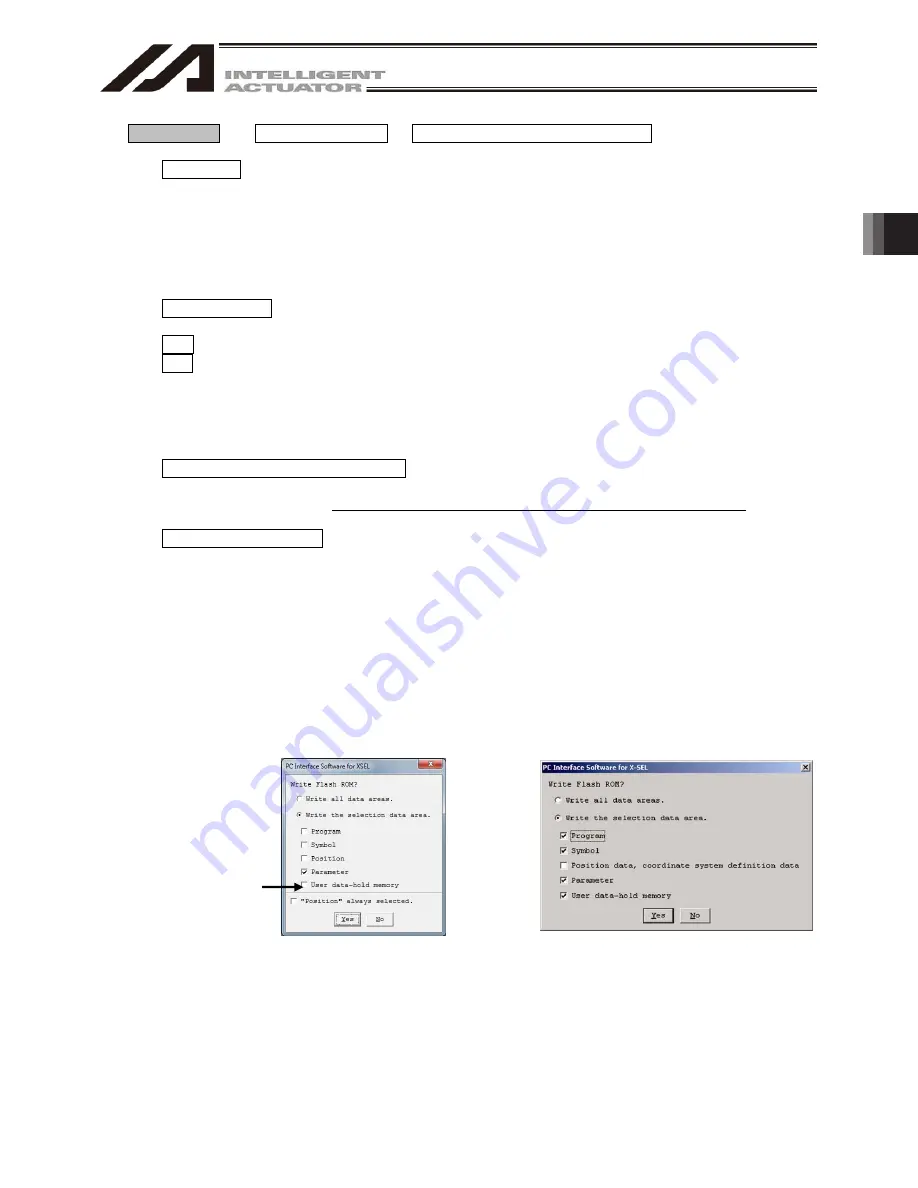
[9] Write to Flash ROM (W) Clear the data areas in the flash ROM and then write the data saved in the
controller’s RAM to the flash ROM.
For SSEL, ASEL, PSEL and X-SEL-P/Q, PX/QX (w/gateway function), R/S, RX/SX, RXD/SXD,
RA/SA, RAX/SAX, RAXD/SAXD compatible with increased memory, you can choose to write either
all the data range or selected data range (PC interface software version 7.2.0.0 or later).
Writing all the data range:
All data from the user data retained memory including program,
symbol, position, parameter, X-SEL-P/Q, PX/QX, R/S, RX/SX,
and RXD/SXD will be written to the flash ROM.
Writing the selected data range: Only the selected data will be written to the flash ROM.
* There is a limit in the number of writing to the flash ROM (write limit: about 100,000 times). If you
do not want to write all the data, select “Select the data range” and write to the flash ROM.
Fig. 3.27 Confirmation (X-SEL-P/Q, R/S,
RX/SX, RXD/SXD, RA/SA, RAX/SAX,
RAXD/SAXD, SSEL, ASEL, PSEL)
Fig. 3.28 Confirmation (X-SEL-PX/QX)
XSEL-RA/SA, RAX/SAX,
RAXD/SAXD, SSEL,
ASEL and PSEL will
not be displayed.
Summary of Contents for IA-101-X-MW
Page 2: ......
Page 4: ......
Page 8: ......
Page 50: ...1 Before You Begin 42 1 4 Connection to Controller Fig 1 48 X SEL K J Type Controller...
Page 52: ...1 Before You Begin 44 Figure shows example of TT Fig 1 50 Table Top Actuator TT TTA...
Page 53: ...1 Before You Begin 45 Fig 1 51 X SEL KX JX Type Controller...
Page 62: ...1 Before You Begin 54 Fig 1 60 ASEL Type Controller USB Cable...
Page 63: ...1 Before You Begin 55 Fig 1 61 PSEL Type Controller USB Cable...
Page 189: ...9 Symbol Edit Window 181...
Page 251: ...13 How to Reset an Absolute Encoder 243 Fig 13 38 Arm Length 120 Reference Position...
Page 386: ...16 Appendix 378...
Page 391: ......


