background image

19

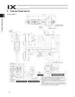
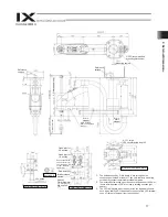
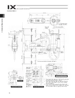
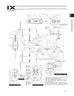
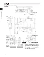
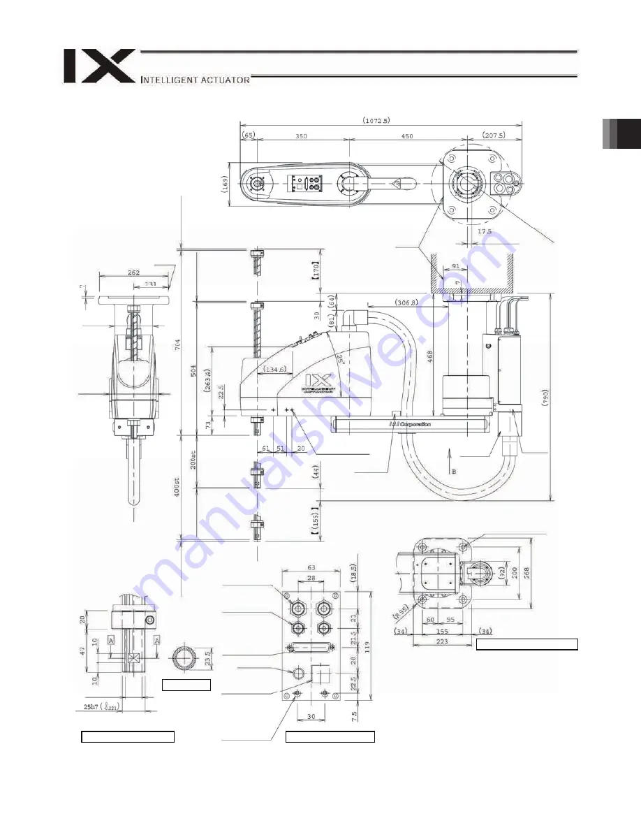
2. External Dimensions

black

red yellow

white

IX-HNN-80

H

Reference 
surface 

(Mounting center) 

310 (recommended 

mounting dimension)

Reference 
surface 

6 (Mechani

cal e

nd)


6 (Mechani

cal e

nd)


Arm 2 
stopper

3-M4, depth 8

Same on opposite 

side (*1) 

Arm 1 
stopper 

Quick joint for 

6 air tube 

Quick joint for 

4 air tube 

User connector (D-
sub connector for 
user wiring, 25-pin, 
socket, fastener 
size M2.6) 

ALM (*3) 

Spacer

Outer diameter 

7, height 10, 

M4, depth 5 

(*2)

Detail view of panel (1/2)

Detail view of arm tip (1/2)

18 hollow 

Section A-A

B: Detail view of base mount

4-

14, board 

24 counterbored, depth 5

*1:  The prepared holes denoted by “3-M4, depth 8” are through 

holes connecting the side faces of the arm. 

*2:  The external force acting upon the spacer shall be kept to 

30 N or less in axial direction or 2 N-m or less in rotating 
direction (per spacer). 

*3:  The LED will actuate when the user wires the applicable 

lines in such a way that 24 VDC is applied to the user-wired 
LED terminal upon output of a signal from the controller.

Arm 2 
stopper

* The inverse specification is installed upside down. 

BK switch 
(brake release 
switch)

(

144) 

(

188) 

6 (Mechani

cal e

nd)


6 (Mechani

cal e

nd)


Summary of Contents for IX Series

Page 1: ...Horizontal Articulated Robot IX Series For Ceiling Mount Arm Length 500 600 700 800 Operation Manual Seventh Edition ...

Page 2: ......

Page 3: ...ading the Operation Manual keep it in a convenient place so that whoever is handling this product can reference it quickly when necessary Important This Operation Manual is original The product cannot be operated in any way unless expressly specified in this Operation Manual IAI shall assume no responsibility for the outcome of any operation not specified herein Information contained in this Opera...

Page 4: ......

Page 5: ...del Nameplate 30 6 4 How to Read Model Number 31 7 Specifications 32 7 1 IX HNN50 H 60 H 70 H 80 H 32 7 2 IX INN50 H 60 H 70 H 80 H 40 8 Installation Environment and Storage Environment 48 8 1 Installation Environment 48 8 2 Installation Platform 48 8 3 Storage Preservatoin Environment 49 9 How to Install 50 9 1 Installation Posture 50 9 3 Installing the Robot 53 10 Connecting the Controller 54 11...

Page 6: ...t Visual Check 76 13 6 How to Measure Lost Motion 77 13 8 Absolute Encoder Reset Method 80 13 8 1 Preparation for Absolute Reset 80 13 8 2 Starting the Absolute Reset Menu 81 13 8 3 Absolute Reset Procedure for Arm 1 or 2 82 13 8 4 Absolute Reset Procedure for the Rotational Axis Vertical Axis 87 14 Warranty Period and Scope of Warranty 95 Change History 97 95 95 95 95 96 96 14 1 Warranty Period 1...

Page 7: ...ant safety parts of machinery Safety device etc Do not use the product outside the specifications Failure to do so may considerably shorten the life of the product Do not use it in any of the following environments 1 Location where there is any inflammable gas inflammable object or explosive 2 Place with potential exposure to radiation 3 Location with the ambient temperature or relative humidity e...

Page 8: ...he safety factor of the hook in such factors as shear strength Do not get on the load that is hung on a crane Do not leave a load hung up with a crane Do not stand under the load that is hung up with a crane 3 Storage and Preservation The storage and preservation environment conforms to the installation environment However especially give consideration to the prevention of condensation Store the p...

Page 9: ...oseness Failure to do so may cause a fire electric shock or malfunction of the product Never cut and or reconnect the cables supplied with the product for the purpose of extending or shortening the cable length Failure to do so may cause the product to malfunction or cause fire 4 Installation and Start 3 Grounding The grounding operation should be performed to prevent an electric shock or electros...

Page 10: ... to secure safety Do not insert a finger or object in the openings in the product Failure to do so may cause an injury electric shock damage to the product or fire When releasing the brake on a vertically oriented actuator exercise precaution not to pinch your hand or damage the work parts with the actuator dropped by gravity 5 Teaching When the work is carried out with 2 or more persons make it c...

Page 11: ...minal block or any of the various setting switches in the power ON mode Failure to do so may result in an electric shock or malfunction 7 Automatic Operation Check before starting the automatic operation or rebooting after operation stop that there is nobody in the safety protection fence Before starting automatic operation make sure that all peripheral equipment is in an automatic operation ready...

Page 12: ...sult in a damage to the product When releasing the brake on a vertically oriented actuator exercise precaution not to pinch your hand or damage the work parts with the actuator dropped by gravity The slider or rod may get misaligned OFF the stop position if the servo is turned OFF Be careful not to get injured or damaged due to an unnecessary operation Pay attention not to lose the cover or untigh...

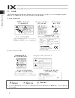
Page 13: ...e product is not handled correctly will result in death or serious injury Danger Warning This indicates a potentially hazardous situation which if the product is not handled correctly could result in death or serious injury Warning Caution This indicates a potentially hazardous situation which if the product is not handled correctly may result in minor injury or property damage Caution Notice This...

Page 14: ...Handling of the Carton Each robot is packed with a controller prior to shipment When transporting the carton containing the robot and controller observe the following items and be careful not to drop the carton or apply impact due to forcible contact If the carton is heavy one operator should not attempt to carry it alone Place the carton on a level surface if it is to be left there for a while Do...

Page 15: ...at requires specified skills it must be operated performed by a person having the proper qualifications 4 Handling of Individual Components The robot and controller are supplied as a set Your robot cannot be used with the controller supplied with another robot When handling multiple robots check that the serial number printed on each of the robot main bodies and the serial number of the correspond...

Page 16: ...plates and let arms 1 and 2 extend straight Loop the cables around the base and secure them with adhesive tape etc or secure the cables to the transporting stays with adhesive tape etc If a crane is used install the supplied eye bolts 4 pcs on the transporting stays Remove the arm locking plates let arms 1 and 2 extend straight and transport the robot in the posture shown below Transporting postur...

Page 17: ...our back or drop the robot onto your feet If the robot drops during transport you may be pinned down and sustain serious injury Never stand underneath the robot while it is suspended Use an appropriate hoist and ropes whose payload is sufficiently greater than the mass of the robot If any machine or means is used that requires a specified qualification it must be operated by a person having the re...

Page 18: ... International Standards Compliances This actuator complies with the following overseas standard Refer to Overseas Standard Compliance Manual ME0287 for more detailed information RoHS Directive CE Marking ...

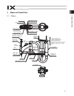
Page 19: ...is 3 vertical axis Reference surface Ball screw spline shaft Axis 3 vertical axis Cover arm 2 Axis 4 rotational axis Panel Mechanical stopper for axis 3 vertical axis Arm 2 End face cover arm 1 Arm 1 Wiring duct M cable outside robot PG cable outside robot U cable outside robot Air tubes 4 x 2 pcs 6 x 2 pcs BK power supply cable outside robot Cover base Mechanical stopper for arm 1 arm 2 Axis 1 Co...

Page 20: ...n the labels may result in serious injury or damage to the robot Prohibition of entry into the operation area Warning on handling of the vertical axis Warning against electric shock Robot model nameplate CE certified robot Provided only for CE certified models 2 Labels on the Controller Caution warning on handling of the controller Designation of the connected robot Controller model nameplate Othe...

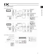
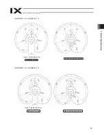
Page 21: ...ing of the vertical axis CE certified robot Provided only for CE certified models Robot serial number View A Warning against electric shock Prohibition of entry into the operation area Ceiling mount specification Inverse specification Warning on handling of the vertical axis Robot serial number View A Warning against electric shock CE certified robot Provided only for CE certified models Prohibiti...

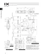
Page 22: ...etail vew of arm tip 1 2 14 hollow Section A A B Detail view of base mount 4 11 large 24 counterbored depth 5 1 The holes denoted by 3 M4 depth 8 are through holes connecting both sides of the arm Take note that long mounting screws may contact the internal mechanism parts 2 The external force acting upon the spacer shall be kept to 30 N or less in axial direction or 2 N m or less in rotating dire...

Page 23: ...10 M4 depth 5 2 Detail view of panel 1 2 Detail view of arm tip 1 2 14 hollow Section A A B Detail View of Base Mount 4 11 large 24 counterbored depth 5 1 The holes denoted by 3 M4 depth 8 are through holes connecting both sides of the arm Take note that long mounting screws may contact the internal mechanism parts 2 The external force acting upon the spacer shall be kept to 30 N or less in axial ...

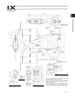
Page 24: ...w of panel 1 2 Detail view of arm tip 1 2 14 hollow Section A A B Detail view of base mount 4 14 board 30 counterbored depth 5 1 The prepared holes denoted by 3 M4 depth 8 are through holes connecting the side faces of the arm 2 The external force acting upon the spacer shall be kept to 30 N or less in axial direction or 2 N m or less in rotating direction per spacer 3 The LED will actuate when th...

Page 25: ...il view of arm tip 1 2 18 hollow Section A A B Detail view of base mount 4 14 board 24 counterbored depth 5 1 The prepared holes denoted by 3 M4 depth 8 are through holes connecting the side faces of the arm 2 The external force acting upon the spacer shall be kept to 30 N or less in axial direction or 2 N m or less in rotating direction per spacer 3 The LED will actuate when the user wires the ap...

Page 26: ...anel 1 2 Detail view of arm tip 1 2 14 hollow Section A A B Detail view of base mount 4 11 large 24 counterbored depth 5 1 The holes denoted by 3 M4 depth 8 are through holes connecting both sides of the arm Take note that long mounting screws may contact the internal mechanism parts 2 The external force acting upon the spacer shall be kept to 30 N or less in axial direction or 2 N m or less in ro...

Page 27: ...l 1 2 Detail view of arm tip 1 2 14 hollow Section A A B Detail view of base mount 4 11 large 24 counterbored depth 5 1 The holes denoted by 3 M4 depth 8 are through holes connecting both sides of the arm Take note that long mounting screws may contact the internal mechanism parts 2 The external force acting upon the spacer shall be kept to 30 N or less in axial direction or 2 N m or less in rotat...

Page 28: ...il view of arm tip 1 2 18 hollow Section A A B Detail view of base mount 4 14 large 30 counterbored depth 5 1 The prepared holes denoted by 3 M4 depth 8 are through holes connecting the side faces of the arm 2 The external force acting upon the spacer shall be kept to 30 N or less in axial direction or 2 N m or less in rotating direction per spacer 3 The LED will actuate when the user wires the ap...

Page 29: ...il view of arm end 1 2 18 hollow Section A A B Detail view of base mount 4 14 large 30 counterbored depth 5 1 The prepared holes denoted by 3 M4 depth 8 are through holes connecting the side faces of the arm 2 The external force acting upon the spacer shall be kept to 30 N or less in axial direction or 2 N m or less in rotating direction per spacer 3 The LED will actuate when the user wires the ap...

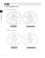
Page 30: ...Operation Area 3 Robot Operation Area IX HNN50 H IX INN50 H IX HNN60 H IX INN60 H Area of prohibited entry Movement range Range of stopper position Area of prohibited entry Movement range Range of stopper position ...

Page 31: ...25 3 Robot Operation Area IX HNN70 H IX INN70 H IX HNN80 H IX INN80 H Area of prohibited entry Movement range Range of stopper position Area of prohibited entry Movement range Range of stopper position ...

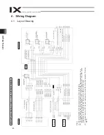
Page 32: ...ignal 4 Wiring Diagram 4 1 Layout Drawing Flexible cable Brake power terminals User wiring terminals Cable fix cap Capcon M cable outside robot Servo motor for axis 1 arm 1 PG cable inside robot M cable inside robot U cable inside robot Axis 2 arm 2 servo motor Axis 3 Z axis servo motor with brake Axis 4 R axis servo motor FG to D sub housing D sub connector for user wiring 15 pin socket Alarm LED...

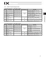
Page 33: ...C rated AWG18 0 84e flexible cable UL VW 1 c UL FT 1 6 M cable outside robot IAI Wire 300 V 80 C rated AWG18 0 89e flexible cable UL VW 1 c UL FT 1 IX HNN70 H 80 H IX INN70 H 80 H No Code name Model number Manufacturer Remarks 1 Axis 1 servo motor TS4614 N2077 E209 800 750 W key groove CE certified 2 Axis 2 servo motor TS4609 N2077 E206 60 400 W key groove CE certified 3 Axis 3 servo motor w brake...

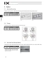
Page 34: ...l a load at the end of the Z axis arm Model number Remarks IX FL 1 For arm length 500 600 IX FL 3 For arm length 700 800 5 3 Absolute Data Backup Battery This battery is used to retain absolute data in the encoder Set the battery inside the cover of the SCARA robot Model number Remarks AB 3 For arm length 250 800 Four batteries are needed for each robot all SCARA robot models Since AB 3 batteries ...

Page 35: ...uded in the Carton s k r a m e R r e b m u n l e d o M m e t I o N 1 Robot Refer to 6 3 How to Read Model Nameplate and 6 4 How to Read Model Number 2 Controller s e i r o s s e c c A 3 Eye bolt 4 D sub connector 5 Hood set for D sub connector 6 Danger label 7 Positioning sticker 8 PIO flat cable 9 First step by step guide 10 Operation manual CD DVD 11 Safety guide ...

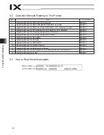
Page 36: ...MW IA 101 X USBMW ME0154 5 Operation Manual for Teaching Pendant SEL T TD TG ME0183 6 Operation Manual for Teaching Pendant IA T X XD ME0160 7 Operation Manual for DeviceNet ME0124 8 Operation Manual for CC Link ME0123 9 Operation Manual for PROFIBUS ME0153 10 Operation Manual for X SEL Ethernet ME0140 12 Operation Manual for Dedicated Terminal Block for Multi point I O Board ME0139 13 Operation M...

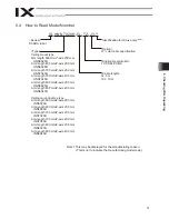
Page 37: ...H Arm length 700 mm Z axis 400 mm HNN7040H Arm length 800 mm Z axis 200 mm HNN8020H Arm length 800 mm Z axis 400 mm HNN8040H Ceiling mount inverse type Arm length 500 mm Z axis 200 mm INN5020H Arm length 600 mm Z axis 200 mm INN6020H Arm length 700 mm Z axis 200 mm INN7020H Arm length 700 mm Z axis 400 mm INN7040H Arm length 800 mm Z axis 200 mm INN8020H Arm length 800 mm Z axis 400 mm INN8040H No...

Page 38: ...2 maximum composite speed 6381 Axis 3 vertical axis mm sec 1473 Maximum operating speed 2 Axis 4 rotational axis degree sec 1857 Axis 1 Axis 2 0 010 Axis 3 vertical axis mm 0 010 Positioning repeatability precision 3 Axis 4 rotational axis degree 0 005 Cycle time 4 sec 0 39 Rated 2 Load capacity Maximum kg 10 Upper limit 8 181 0 18 5 Push torque limit 70 Axis 3 vertical axis Push force control ran...

Page 39: ...ed position from multiple positions or any of the operating conditions such as operating speed and acceleration deceleration setting is changed 4 Measured when the robot is operated at the maximum speed carrying a load of 2 kg 5 Equivalent allowable inertial moment at the center of rotation of axis 4 The offset from the center of rotation of axis 4 to the center of gravity of the tool shall be 50 ...

Page 40: ...e speed 7232 Axis 3 vertical axis mm sec 1473 Maximum operating speed 2 Axis 4 rotational axis degree sec 1857 Axis 1 Axis 2 0 010 Axis 3 vertical axis mm 0 010 Positioning repeatability precision 3 Axis 4 rotational axis degree 0 005 Cycle time 4 sec 0 43 Rated 2 Load capacity Maximum kg 10 Upper limit 8 181 0 18 5 Push torque limit 70 Axis 3 vertical axis Push force control range Lower limit 9 N...

Page 41: ...ed position from multiple positions or any of the operating conditions such as operating speed and acceleration deceleration setting is changed 4 Measured when the robot is operated at the maximum speed carrying a load of 2 kg 5 Equivalent allowable inertial moment at the center of rotation of axis 4 The offset from the center of rotation of axis 4 to the center of gravity of the tool shall be 50 ...

Page 42: ...te speed 7010 Axis 3 vertical axis mm sec 1614 Maximum operating speed 2 Axis 4 rotational axis degree sec 1266 Axis 1 Axis 2 0 015 Axis 3 vertical axis mm 0 010 Positioning repeatability precision 3 Axis 4 rotational axis degree 0 005 Cycle time 4 sec 0 42 Rated 5 Load capacity Maximum kg 20 Upper limit 8 304 31 0 Push torque limit 70 Axis 3 vertical axis Push force control range Lower limit 9 N ...

Page 43: ...d position from multiple positions or any of the operating conditions such as operating speed and acceleration deceleration setting is changed 4 Measured when the robot is operated at the maximum speed carrying a load of 2 kg 5 Equivalent allowable inertial moment at the center of rotation of axis 4 The offset from the center of rotation of axis 4 to the center of gravity of the tool shall be 50 m...

Page 44: ...te speed 7586 Axis 3 vertical axis mm sec 1614 Maximum operating speed 2 Axis 4 rotational axis degree sec 1266 Axis 1 Axis 2 0 015 Axis 3 vertical axis mm 0 010 Positioning repeatability precision 3 Axis 4 rotational axis degree 0 005 Cycle time 4 sec 0 43 Rated 5 Load capacity Maximum kg 20 Upper limit 8 304 31 0 Push torque limit 70 Axis 3 vertical axis Push force control range Lower limit 9 N ...

Page 45: ...d position from multiple positions or any of the operating conditions such as operating speed and acceleration deceleration setting is changed 4 Measured when the robot is operated at the maximum speed carrying a load of 2 kg 5 Equivalent allowable inertial moment at the center of rotation of axis 4 The offset from the center of rotation of axis 4 to the center of gravity of the tool shall be 50 m...

Page 46: ...composite speed 6381 Axis 3 vertical axis mm sec 1473 Maximum operating speed 2 Axis 4 rotational axis degree sec 1857 Axis 1 Axis 2 0 010 Axis 3 vertical axis mm 0 010 Positioning repeatability precision 3 Axis 4 rotational axis degree 0 005 Cycle time 4 sec 0 39 Rated 2 Load capacity Maximum kg 10 Upper limit 8 181 18 5 Push torque limit 70 Axis 3 vertical axis Push force control range Lower lim...

Page 47: ...ed position from multiple positions or any of the operating conditions such as operating speed and acceleration deceleration setting is changed 4 Measured when the robot is operated at the maximum speed carrying a load of 2 kg 5 Equivalent allowable inertial moment at the center of rotation of axis 4 The offset from the center of rotation of axis 4 to the center of gravity of the tool shall be 50 ...

Page 48: ...speed 7232 Axis 3 vertical axis mm sec 1473 Maximum operating speed 2 Axis 4 rotational axis degree sec 1857 Axis 1 Axis 2 0 010 Axis 3 vertical axis mm 0 010 Positioning repeatability precision 3 Axis 4 rotational axis degree 0 005 Cycle time 4 sec 0 43 Rated 2 Load capacity Maximum kg 10 Upper limit 8 181 18 5 Push torque limit 70 Axis 3 vertical axis Push force control range Lower limit 9 N kgf...

Page 49: ...ed position from multiple positions or any of the operating conditions such as operating speed and acceleration deceleration setting is changed 4 Measured when the robot is operated at the maximum speed carrying a load of 2 kg 5 Equivalent allowable inertial moment at the center of rotation of axis 4 The offset from the center of rotation of axis 4 to the center of gravity of the tool shall be 50 ...

Page 50: ...speed 7010 Axis 3 vertical axis mm sec 1614 Maximum operating speed 2 Axis 4 rotational axis degree sec 1266 Axis 1 Axis 2 0 015 Axis 3 vertical axis mm 0 010 Positioning repeatability precision 3 Axis 4 rotational axis degree 0 005 Cycle time 4 sec 0 42 Rated 5 Load capacity Maximum kg 20 Upper limit 8 304 31 0 Push torque limit 70 Axis 3 vertical axis Push force control range Lower limit 9 N kgf...

Page 51: ...d position from multiple positions or any of the operating conditions such as operating speed and acceleration deceleration setting is changed 4 Measured when the robot is operated at the maximum speed carrying a load of 2 kg 5 Equivalent allowable inertial moment at the center of rotation of axis 4 The offset from the center of rotation of axis 4 to the center of gravity of the tool shall be 50 m...

Page 52: ...speed 7586 Axis 3 vertical axis mm sec 1614 Maximum operating speed 2 Axis 4 rotational axis degree sec 1266 Axis 1 Axis 2 0 015 Axis 3 vertical axis mm 0 010 Positioning repeatability precision 3 Axis 4 rotational axis degree 0 005 Cycle time 4 sec 0 43 Rated 5 Load capacity Maximum kg 20 Upper limit 8 304 31 0 Push torque limit 70 Axis 3 vertical axis Push force control range Lower limit 9 N kgf...

Page 53: ...d position from multiple positions or any of the operating conditions such as operating speed and acceleration deceleration setting is changed 4 Measured when the robot is operated at the maximum speed carrying a load of 2 kg 5 Equivalent allowable inertial moment at the center of rotation of axis 4 The offset from the center of rotation of axis 4 to the center of gravity of the tool shall be 50 m...

Page 54: ...l the robot receives a significant reactive force Be certain the platform has sufficient rigidity to withstand the anticipated force The surface on which the robot is fixed must have a thickness of 25 mm or more The levelness of the robot installation surface must be at least 0 05 mm Machine tapped holes of the size shown in the table below in the mounting surface of the platform Model number Tapp...

Page 55: ...ept in an environment subject to condensation provide preventive measures from over the carton or directly to the robot after unpacking The maximum storage preservation temperature is 60 C for a short storage preservation period If the robot is to be stored for more than a month the temperature should not exceed 50 C Failure to provide a proper environment for installation and storage preservation...

Page 56: ...50 9 How to Install ...

Page 57: ...n in the case of the ceiling mount specification or to the bottom position in the case of the inverse specification home return operation Therefore install the robot in such a way that the vertical axis will not collide with the ceiling or platform during an absolute reset It is recommended that the pedestal be constructed in such a way that contact with the robot will not occur within the robot s...

Page 58: ...52 9 How to Install Center of recommended installation part ...

Page 59: ... M12 104 N m For the hex bolts use high tension bolts with an ISO rating of 10 9 or higher Always insert a washer below each bolt Without a washer the bolt bearing surface may sink Tighten the hex bolts securely to the correct torque Improperly tightened bolts may reduce the accuracy of robot operation and in the worst case cause the robot to overturn Warning Caution 4 11 hole 24 counterbore depth...

Page 60: ... a cable always turn off the power to the controller Connecting disconnecting a cable with the power supplied to the controller may cause the robot to malfunction resulting in a serious accident Installing the connectors into the wrong sockets may cause the robot to malfunction Be sure to check the designation on the cable with that on the controller panel before plugging in any connector If the c...

Page 61: ...le always turn off the power to the controller Connecting disconnecting a cable with the power supplied to the controller may cause the robot to malfunction resulting in a serious accident Installing the connectors into the wrong sockets may cause the robot to malfunction Be sure to check the designation on the cable with that on the controller panel before plugging in any connector If the connect...

Page 62: ... V power supply Example of X SEL PX controller 4 axis SCARA robot of arm length 250 to 600 mm without I O expansion SCARA robot If you are using an X SEL PX QX controller you must supply the brake power to the controller in addition to wiring the brake power cable from the SCARA robot Supply the brake power 24 V to the controller as shown in the figure ...

Page 63: ...k the following items Visually check the robot controller and cables for dents and other abnormalities Confirm that the cables are connected properly and that the connectors are inserted securely Warning Failure to perform these checks may result in a malfunctioning robot or a damaged controller or robot ...

Page 64: ...range for continuous operation Reference range of duty for continuous operation duty Duty Inertial moment kg m2 Duty Continuous operation Continuous operation Stopping time 100 Mass of carrying load kg Axis 4 rotational axis only Acceleration deceleration Acceleration deceleration IX arm length 700 800 Reference settings for PTP acceleration deceleration IX arm length 700 800 Reference duties for ...

Page 65: ...ration Continuous operation Stopping time 100 Mass of carrying load kg Acceleration deceleration G Acceleration deceleration IX arm length 600 Reference settings for PTP acceleration deceleration IX arm length 600 Reference duties for CP continuous operation Maximum setting range Reference range for continuous operation Reference range of duty for continuous operation duty Duty Duty Continuous ope...

Page 66: ...ing time 100 Mass of carrying load kg Acceleration deceleration G Acceleration deceleration G IX arm length 800 Reference settings for PTP acceleration deceleration IX arm length 800 Reference duties for CP continuous operation Maximum setting range Reference range for continuous operation Reference range of duty for continuous operation duty Duty Duty Continuous operation Continuous operation Sto...

Page 67: ...ration appropriate for the applicable mass and inertial moment If not the life of the driving part may be shortened or damage or vibration may result If an overload error error code D0A occurs lower the acceleration deceleration setting or provide an appropriate stopping time based on the reference duty for continuous operation Duty Continuous operation Continuous operation Stopping time 100 To mo...

Page 68: ...raph of push force and push torque limit during positioning shows characteristics when no load is installed on the vertical axis In downward push motion operation the applicable push force increases by the load mass In upward push motion operation with the inverse specification the applicable push force decreases by the load mass Push force is controlled by servo motor current No control is implem...

Page 69: ...or the tool interferes with peripheral equipment decrease the soft limits to reduce the operation area Also keep the inertial moment of the tool and load at the allowable value or less Refer to 11 4 Carrying Load Use the D cut surface at the end of axis 4 rotational axis to adjust the position direction of axis 4 To set the rotating direction using the D cut surface and setscrews be sure to use se...

Page 70: ...may break while the robot is operating and cause the tool to detach and fly off If the tool diameter exceeds 100 mm the tool will contact the robot within the robot s operation area causing damage to the tool load and or robot Avoid attachment of the tool at the D cut surface via thread fastening Doing so may damage the D cut positioning surface Caution Warning ...

Page 71: ...cording to the mass of the end and moment of inertia Failure to do so may cause the drive part to wear prematurely or may result in damage or vibration If vibration occurs lower the acceleration deceleration as appropriate If the load gets offset the robot becomes more likely to cause vibration Design the tools so that the load s center of gravity aligns with the center of axis 4 Do not move the r...

Page 72: ... Other Twisted pair cable 1 to 24 shielded Piping specifications Normal service pressure 0 8 MPa 4 mm x 2 5 mm 2 pieces Dimensions outer diameter x inner diameter and number of tubes 6 mm x 4 mm 2 pieces Working medium Air ALM indicator specifications Rated voltage 24 VDC Rated current 12 mA Illumination color Red LED Quick joint 6 red ALM indicator Spacer for user part installation Quick joint 6 ...

Page 73: ...pin plug Solder a user supplied cable to the D sub connector plug attach the supplied hood and then connect to the user connector socket Use a shielded cable with an outer diameter of 11 or less To turn on the ALM indicator the user must configure a dedicated circuit that uses the controller I O output signal etc User connector pins and corresponding Y terminals Before commencing wiring piping wor...

Page 74: ...ctions properly 2 Half a Year Maintenance Inspection Have a maintenance and inspection for the following items once in half a year every 6 months If the robot main body has flaws or other abnormalities please contact IAI Maintenance Inspection Area Maintenance Inspection Details Robot Main Body Check for any looseness of the attachment bolts on the robot body and play on cover related components T...

Page 75: ...ment of the timing belt is required If any defect is found contact IAI Refer to 13 5 Third Axis Timing Belt Visual Check Note 1 In case the duty of the robot operation is high or ambient temperature is high supply the grease frequently every year 5 5 Years Maintenance Inspection Have a maintenance and inspection for the following items once every 5 years After 5 years has passed have a maintenance...

Page 76: ... Yushi Multemp LRL No 3 Dustproof Splash proof type and Clean type THK AFE Every half a year For the types except for dust and rainproof type the use of the following grease is also available Types Grease to Apply Supply Period Other Types than Dustproof Splash proof type and Clean type THK AFG Every half a year Caution Do not attempt to apply fluorine grease When mixed with lithium grease or urea...

Page 77: ...p and down so that grease is spread smoothly all over the inside bearing Apply grease Model Quantity Arm Length 500 600 8 to 16 cc 7 to 14g Arm Length 700 800 10 to 20 cc 9 to 18g 4 Wipe off excessive grease on the ball screw spline axis surface to the extent that grease does not fly off when the spline axis is operated Apply Grease Apply Grease Caution In case the grease got into your eye immedia...

Page 78: ...for each axis using the hex wrench Tighten if any loosened screw is found 4 Attach the cover Tightenting torque for M3 flat head screw is 0 74 N m Ist Axis Mounting Screw 2nd Axis Mounting Screw Cover Arm 1 M3 Flat head Screw Tightening Torque N m Arm Length 1st axis 2nd axis Remarks 500 600 30 0 12 3 1st axis Hexagon soket head screws M8 strength class 10 9 2nd axis Hexagon soket head screws M6 s...

Page 79: ... The following items are required when replacing the batteries Before replacing the batteries turn off the power to the controller control panel and other relevant units Model number Tool New 1x only specification IX HNN50 H 60 H 70 H 80 H IX INN50 H 60 H 70 H 80 H Phillips screwdriver AB3 4 pcs ...

Page 80: ...f new batteries are not connected for a longer period the rotation data will be lost and an absolute reset will become necessary Replace batteries one axis at a time If the batteries for all axes are replaced at once the work may not be completed within the specified time 4 Install the batteries into the battery holder Battery holder Battery for axis 4 Battery connector 3 for axis 3 Battery for ax...

Page 81: ...alling the cover base be careful not to pinch the internal wiring Instead of tightening to the specified torque in one go loosely position each screw in the position shown to the left and while pressing the cover in the direction of the arrow tighten both screws uniformly to secure the cover effectively with the gasket Caution ...

Page 82: ...tenance and Inspection 13 5 Third Axis Timing Belt Visual Check Tool necessary for work Penlight Procedure Check the timing belt surface using a penlight as shown in the pictures for any defect or excessive wear ...

Page 83: ...on Negative Direction Positive Direction Positive Direction Mesurement Point Mesurement Redius Mesurement Point Mesurement Redius 100mm 100mm 5 0 5 5 0 5 a Move the axis from 5deg towards 0deg the measurement point in the positive direction and measure the position b After moving from 0deg towards 5deg in the positive direction move it from 5deg towards 0deg the measurement point in the negative d...

Page 84: ...erage 0 0013 0 0021 Difference mm 0 0013 0 0021 0 0034 Measurement Radius mm 100 Lost Motion arc min atan 0 0034 100 60 nearly equals 0 12 How to decide It is normal as long as the figured out values are below the allowable values shown in the table below Lost Motion Allowance Model Name Lost Motion arc min Measurement Radius mm 1st axis 2nd axis IX HNN50 H 60 H IX INN50 H 60 H IX HNN70 H 80 H IX ...

Page 85: ...k Penlight Hex Wrench Set Phillips Screwdriver M3 Flat head screw Procedure 1 Move the up down axis to the position of 50 to 100mm 2 Remove the set screw for the arm 2 lower cover 3 Check the timing belt surface using a penlight for any defect or excessive wear 4 Attach the cover Check it visually ...

Page 86: ...h operation beforehand An absolute reset of the rotational and vertical axes requires absolute reset adjustment jigs but jigs are not always required for an absolute reset of arms 1 and 2 A multi rotation reset can be performed as long as the current position is within 1 graduation on the positioning mark sticker Example of Absolute Reset Adjustment Jig Model number JG 1 Fully understand the appli...

Page 87: ...Axis Y if you are using an X SEL PX QX controller Starting Up Absolute Reset Window 2 The Abs Encoder Reset window opens One of three absolute reset screens for arm 1 arm 2 and rotational axis vertical axis is displayed when a corresponding tab is clicked Absolute Reset Window Abs Encoder Reset screen for arm 1 or Abs Encoder Reset screen for rotational axis ...

Page 88: ...tenance and Inspection 13 8 3 Absolute Reset Procedure for Arm 1 or 2 1 Click the Encoder Rotation Data Reset1 button Encoder Multi rotation Data Reset 1 2 Click the Reset Controller Error button Controller Reset ...

Page 89: ...ce and Inspection 3 Click the Servo ON button Servo ON 4 Jog the arm to near the reference position see reference position drawing in step 7 and click the Jog end button Jogging 5 Click the Servo OFF button Servo OFF ...

Page 90: ...in on arm 2 to secure the arm in its reference position You can move arm 1 when securing arm 2 Set the jig after confirming that the emergency stop switch is pressed Set the jig after adjusting the arm to the reference position using the positioning mark label as a guide Arm 1 has a cover not arm 2 which is fixed with setscrews Remove the setscrews and detach the cover before setting the jig It is...

Page 91: ...85 13 Maintenance and Inspection 8 Click the OK button Fig 13 18 Confirmation 9 Click the Encoder Rotation Data Reset2 button Encoder Multi rotation Data Reset 2 ...

Page 92: ...eset value to be updated automatically by mistake do not write the updated data to the flash ROM Instead perform a software reset After the software reset the data will return to the original condition before the home preset value was automatically updated Always click the OK button after removing the jig and releasing the emergency stop switch Confirmation 13 Click X in the top right hand corner ...

Page 93: ...d Inspection 13 8 4 Absolute Reset Procedure for the Rotational Axis Vertical Axis 1 Click Encoder Rotation Data Reset1 button Encoder Multi rotation Data Reset 1 2 Click the Reset Controller Error button Controller Reset ...

Page 94: ...re standby button The vertical axis returns to its home position Exercise caution so as not to be injured by the axis during movement Standing By at Tentative Home Position 5 Jog the rotational axis to the reference position see reference position drawing in step 8 and click the Jog end button Jogging ...

Page 95: ...89 13 Maintenance and Inspection 6 Click the Servo OFF button Servo OFF 7 Press the emergency stop switch ...

Page 96: ...g the plate and pin of the adjustment jig as illustrated below Set the jig after confirming that the emergency stop switch is pressed Set the jigs by using the positioning mark as a reference Make sure the top surface of the stopper roughly matches in height with the bottom surface of arm 2 Ceiling mount specification reference position Inverse specification reference position Always press the eme...

Page 97: ...91 13 Maintenance and Inspection 9 Click the OK button Confirmation 10 Click the Encoder Rotation Data Reset2 button Encoder Multi rotation Data Reset 2 ...

Page 98: ...ntenance and Inspection 11 Click the Home pos automatic update button Automatic Refresh of Home Preset Value 12 Remove the adjustment jig 13 Release the emergency stop switch 14 Click the OK button Confirmation ...

Page 99: ...N button Confirmation 16 Click the Standard posture standby button The vertical axis returns to its home position Exercise caution so as not to be injured by the axis during movement Standing By at Reference Posture 17 Click the Servo OFF button Servo OFF ...

Page 100: ...t3 button Encoder Multi rotation Data Reset 3 19 Click the Home pos automatic update button and then click X in the top right hand corner to exit the absolute reset window After the reset is completed be sure to perform Software reset Automatic Refresh of Home Preset Value ...

Page 101: ...ything other than our product 2 Modification or repair performed by a party other than us unless we have approved such modification or repair 3 Anything that could not be easily predicted with the level of science and technology available at the time of shipment from our company 4 A natural disaster man made disaster incident or accident for which we are not liable 5 Natural fading of paint or oth...

Page 102: ...aining to maintenance or management of human life or health 2 A mechanism or mechanical equipment intended to move or transport people such as a vehicle railway facility or aviation facility 3 Important safety parts of mechanical equipment such as safety devices 4 Equipment used to handle cultural assets art or other irreplaceable items 3 Contact us at the earliest opportunity if our product is to...

Page 103: ...0W P 68 Caution notes added telling to go to see the doctor to have an appropriate treatment when the grease got into an eye P 8 Precautions in Handling Note Certainly attach the Horizontal Articulated Robot by following this operation manual added Fourth edition March 2012 P 87 88 Contents changed in 14 Warranty August 2012 Fifth edition 9 1 Installation Posture added P 51 Grease applied to ball ...

Page 104: ......

Page 105: ......

Page 106: ...6 889524 SHANGHAI JIAHUA BUSINESS CENTER A8 303 808 Hongqiao Rd Shanghai 200030 China TEL 021 6448 4753 FAX 021 6448 3992 website www iai robot com 825 PhairojKijja Tower 12th Floor Bangna Trad RD Bangna Bangna Bangkok 10260 Thailand TEL 66 2 361 4458 FAX 66 2 361 4456 Technical Support available in USA Europe and China Head Office 2690 W 237th Street Torrance CA 90505 TEL 310 891 6015 FAX 310 891...

Reviews: