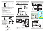
BK
BL
None
WT
RD
BK (V
-
)
BL (CAN L)
Shield
WT (CAN H)
RD (V
+
)
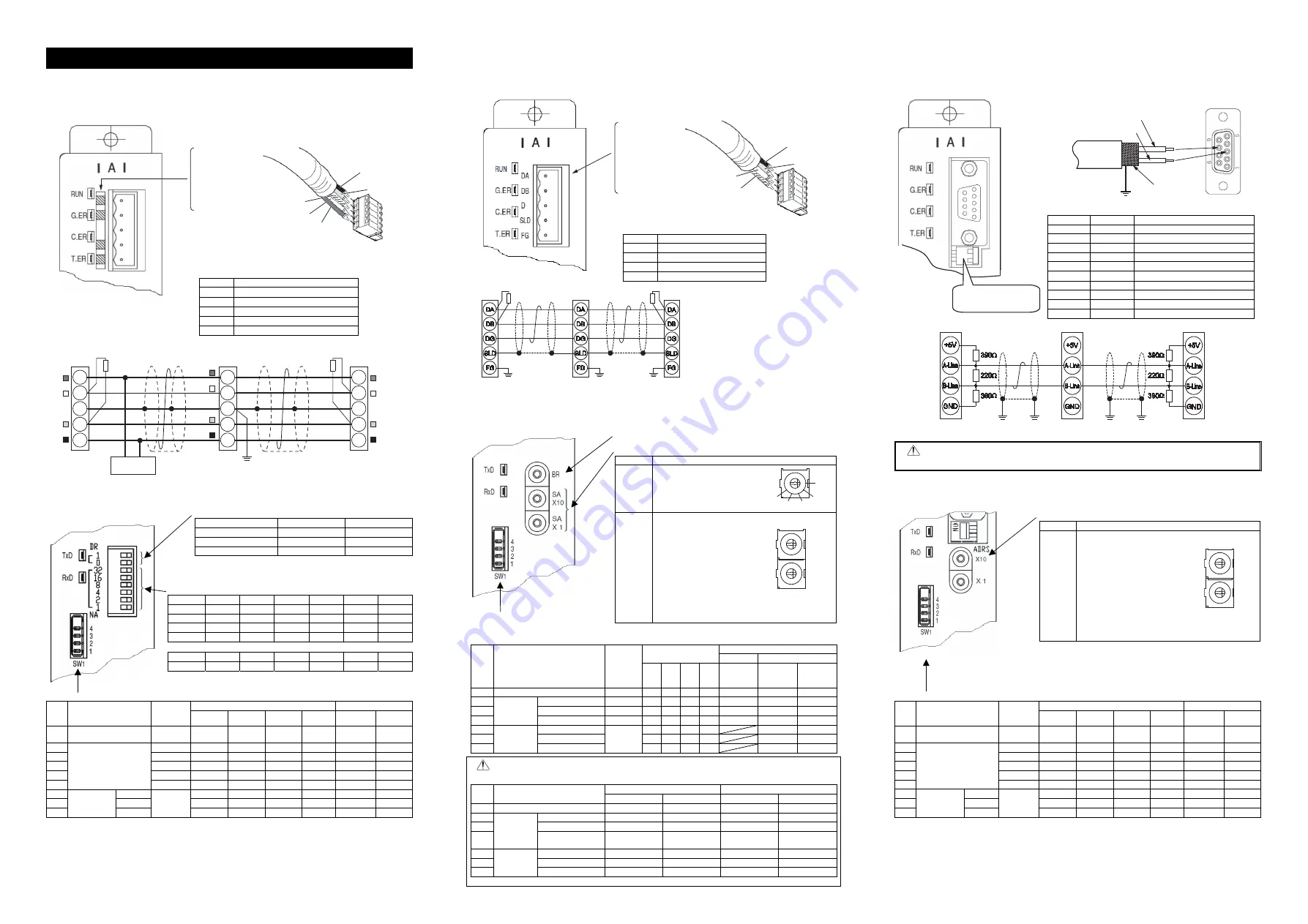
DA (BL)
DB (WT)
DG (YW)
SLD (Shield)
FG (connection is
not required)
BL (DA)
WT (DB)
YW (DG)
Shield (SLD)
Field Network Wirings and Settings
1. DeviceNet (RCM-GW-DV)
[1] Wiring
For details, refer to the Instruction Manuals of the master unit and PLC in which in the master unit is
installed.
The connection connector is enclosed as a standard option.
Connector : SMSTB2.5/5-ST-5.08AU
(Supplier : PHOENIX CONTACT)
There is a sticker attached on the panel showing the corresponding cable
colors.
Use the dedicated cable and connect the wires to the corresponding colors
for the signal identification.
Color Signal Type
RD
Power Supply Cable Positive Side (V
)
WT Communication
Data
High Side (CAN H)
Shield
BL
Communication Data Low Side (CAN L)
BK
Power Supply Cable Negative Side (V
)
[2] Settings for DeviceNet Communication and Operation Modes
Turn off the power before performing this operation. Also, refer to Instruction Manual (DVD) for the
details of the modes.
Baud rate setting switch (Left side is ON)
○
: ON × : OFF
Baud Rate [bps]
DR1
DR0
125k × ×
250k ×
○
500k
○
×
Baud rate is the communication speed, and its unit is bps (bit/sec).
It is necessary that all the settings of the devices have to be the same in
one DeviceNet.
Node address setting switch (Left side is ON)
○
: ON × : OFF
Address
NA32 NA16 NA8 NA4 NA2 NA1
0 × × × × × ×
1 × × × × ×
○
2 × × × ×
○
×
3 × × × ×
○
○
⋮
⋮
⋮
⋮
⋮
⋮
⋮
62
○
○
○
○
○
×
63
○
○
○
○
○
○
The settings have to be made in binary values. Ordinary, the master unit is to be set
to 63.
Mode setting switch (Right side is ON)
○
: ON × : OFF
No. Mode
Max. Number
of Connectable
Axes
Mode Setting Switch
Number of PLC I/O Bytes
*1
4 3 2 1
Input
Output
1
Position Number
specification mode
16 × ×
○
× 48 48
2
Direct numeric
specification mode
4 × × × × 28 52
3 6
×
○
× × 40 76
4 8
○
× × × 52 100
5 10
○
○
×
○
64 124
6 16
○
○
× × 100
196
7
Command
specification
mode
Large
16
Note 1
× × ×
○
160 160
8 Middle ×
×
×
○
128 128
9 Small
○
× ×
○
64 64
Note 1 The numbers of bytes stated in the table above is the maximum data size that can be handled in each mode. This limits
the number of connectable axes. The input and output data size is affected by the total number of the positioner
operation axes and simple direct operation axes.
PLC input
Fixed value (18 bytes)
Number of Positioner Operation Axes
2 bytes
Number of Simple Direct Operation Axes
6 bytes
PLC output
Fixed value (18 bytes)
Number of Positioner Operation Axes
2 bytes
Number of Simple Direct Operation Axes
8 bytes
*1
Number of PLC I/O Bytes: Number of data register occupied by PLC
2 bytes
1 word
1ch
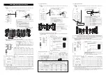
2. CC-Link (RCM-GW-CC)
[1] Wiring
For details, refer to the Instruction Manuals of the master unit and PLC in which in the master unit is
installed.
The connection connector is enclosed as a standard option.
Connector : SMSTB2.5/5-ST-5.08AU
(Supplier : PHOENIX CONTACT)
Use the dedicated cable and connect the wires to the corresponding colors
for the signal identification.
Color Signal Type
BL Communication
Line
A
(DA)
WT
Communication Line B (DB)
YW
Communication Ground Line (DG)
Shield (SLD)
[2] Settings for CC-Link Communication and Operation Modes
Turn off the power before performing this operation. Also, refer to Instruction Manual (DVD) for the
details of the modes.
Baud rate setting switch
Station number setting switch
Switch Description
BR
[Baud rate setting switch]
It establishes the communication
speed.
The setting more than 5 is invalid.
SA
10
SA
1
[Station number setting switch]
Valid settable range is from 1 to 64.
SA
10
ꞏꞏꞏꞏꞏꞏ
It is to set the digit of ten’s
place.
SA
1
ꞏꞏꞏꞏꞏꞏꞏꞏ
It is to set the digit of
one’s place.
(Example) When setting the station number 12:
Set 1 to SA
10.
Set 2 to SA
1.
Ordinary, the master unit is to be set to 00.
Mode setting switch (Right side is ON)
○
: ON × : OFF
No. Mode
Max. Number
of Connectable
Axes
Mode setting switch
PLC Master Unit Setting
Ver.1 Ver.2
4 3 2 1
Number of
occupied
stations
Number of
occupied
stations
Extended
Cyclic
Setting
1
Position number specification mode
14
×
×
○
×
4
4
1
2
Direct numeric
specification
mode
Position Data Limit Mode
14 ×
×
×
× 4
4
1
3
Normal Positioning Mode
7 ×
○
× ×
4
4
1
4
Pressing Available Mode
3 ×
○
○
×
4
4
1
5
Command
specification
mode
Large
16
× × ×
○
3
2
6 Middle
×
○
×
○
3
4
7 Small
○
× ×
○
2
8
Note 1 Although the actual number of used input and output words is as shown below, the areas assigned by the
number of occupied stations set to the master unit and the extended cyclic settings cannot be used for other
purposes. Refer to Instruction Manual (DVD) for the details of the address assignment.
No. Mode
Remote I/O
Data Register
GW
→
PLC (RX) PLC
(RY)
→
GW GW
→
PLC (RWr) PLC (RWw)
→
GW
1
Position number specification mode
7 words
7 words
9 words
9 words
2
Direct numeric
specification
mode
Position Data Limit Mode
7 words
7 words
16 words
16 words
3
Normal Positioning Mode
7 words
7 words
16 words
16 words
4
Pressing Available Mode
2 words
1 byte
6 words
6 words
2 bytes
14 words
5
Command
specification
mode
Large
9 words
9 words
38 words
49 words
6
Middle
9 words
9 words
35 words
45 words
7
Small
9 words
9 words
17 words
21 words
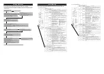
3. PROFIBUS (RCM-GW-PR)
[1] Wiring
For details, refer to the Instruction Manuals of the master unit and PLC in which in the master unit is
installed.
Use the type A cable for PROFIBUS-DP (EN5017).
Use D-Sub 9-pin (female) type of PROFIBUS-DP Standard
(recommended for EN5017) for the connector.
Pin No.
Signal Name
Detail
1 NC
Unconnected
2 NC
Unconnected
3
B-Line
Communication line B (Positive side)
4 NC
Unconnected
5 GND
Signal grounding
6
5V
5V output
7 NC
Unconnected
8 A-Line
Communication
line
A
(Negative side)
9 NC
Unconnected
Housing Shield
Cable
Shield
Note : RCM-GW-PR is equipped with a built-in terminal resistance. If RCM-GW-PR is connected as the terminal,
turn the terminal resistance setting switch ON. If a connector that is equipped with a terminal resistance is
used or RCM-GW-PR is not located on the terminal, keep the switch turned OFF.
[2] Settings for PROFIBUS Communication and Operation Modes
Turn off the power before performing this operation. Also, refer to Instruction Manual (DVD) for the
details of the modes.
Node address setting switch
Switch Description
ADRS
10
1
[Station number setting switch]
Valid settable range is from 3 to 32.
10
ꞏꞏꞏꞏꞏꞏ
It is to set the digit of ten’s
place.
1
ꞏꞏꞏꞏꞏꞏꞏꞏ
It is to set the digit of one’s
place.
(Example) When setting the station number 12:
Set 1 to
10.
Set 2 to
1.
Typically, the master unit is to be set to 02.
Node address 00 is either for the monitor or for the inspection functions
while 01 is for monitoring devices.
Set numbers within the range up to 32 at the maximum in the order of 03, 04,
05, … from the closer to the further from the master unit.
Mode setting switch (Right side is ON)
○
: ON × : OFF
No. Mode
Max. Number
of Connectable
Axes
Mode Setting Switch
Number of PLC I/O Bytes
*1
4 3 2 1
Input
Output
1
Position number
specification mode
16 × ×
○
× 48 48
2
Direct numeric
specification mode
4 × × ×
× 28
52
3 6
×
○
× × 40 76
4 8
○
× × × 52
100
5 10
○
○
×
○
64 124
6 16
○
○
× × 100
196
7
Command
specification
mode
Large
16
Note 1
× × ×
○
160 160
8 Middle ×
○
×
○
128 128
9 Small
○
× ×
○
64 64
Note 1 The numbers of bytes stated in the table above is the maximum data size that can be handled in each mode. This limits
the number of connectable axes. The input and output data size is affected by the total number of the positioner
operation axes and simple direct operation axes.
PLC input
Fixed value (18 bytes)
Number of Positioner Operation Axes
2 bytes
Number of Simple Direct Operation Axes
6 bytes
PLC output
Fixed value (18 bytes)
Number of Positioner Operation Axes
2 bytes
Number of Simple Direct Operation Axes
8 bytes
*1
Number of PLC I/O Bytes: Number of data register occupied by PLC
2 bytes
1 word
1ch
Slave Device
RCM-GW-DV
V+
Drain
(Shield)
CAN_H
CAN_L
V-
RD
WT
BL
BK
RD
WT
BL
BK
V+
Drain
(Shield)
CAN_H
CAN_L
Class D grounding
(Class-III grounding)
V+
Drain
(Shield)
CAN_H
CAN_L
V-
RD
WT
BL
BK
Communication power
needs to be supplied by
an external device.
Terminal Resistance is required
to be mounted on the terminal.
V-
Terminal Resistance
121
Ω
Master Unit
Terminal Resistance
121
Ω
24V
Power Supply
Slave Device
RCM-GW-CC
SLD and FG are internally connected.
Terminal Resistance is required
to be mounted on the terminal.
The terminal resistor differs depending on the type
of the dedicated cable for CC-Link.
• Cable FANC-SBH···130
Ω
1/2W
(High Performance Cable
dedicated for CC-Link)
• Cable FANC-SB······110
Ω
1/2W
(CC-Link Dedicated Cable)
Class D grounding
(Class-III grounding)
Master Unit
Terminal
Resistance
Terminal
Resistance
09
8
7
6
5 4 3 2 1
156k
625k
2.5M
5M
10M
09
8
7
6
5 4 3 2 1
09
8
7
6
5 4 3 2 1
SA
×
10
SA
×
1
RCM-GW-PR
Slave Device
Class D grounding
(Class-III grounding)
Master Unit
09
8
7
6
5 4 3 2 1
09
8
7
6
5 4 3 2 1
×
10
×
1
ADRS
Cable
Shield
Red B line (Positive side)
Green A line (Negative side)
Terminal Resistance
Setting Switch


