98
6.
Operation:
Mode
Flow
Chart
99
6.11 End
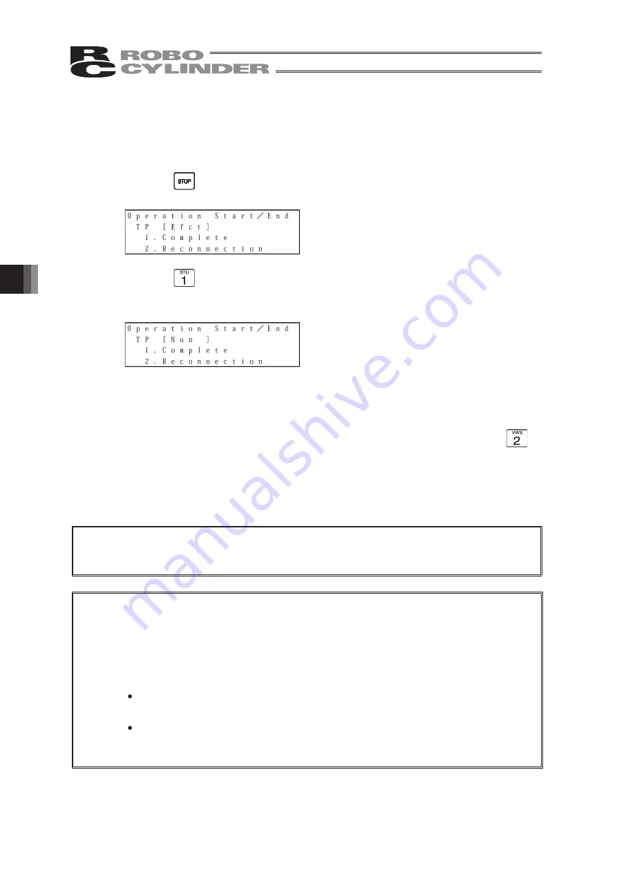
Before removing the Teaching Pendant from the RC controller, be sure to execute End.
Operation:
1. Press the
key for more than 2.5 seconds.
The screen will change to the TP end screen.
2. Press the
key to select “Complete.”
The screen display will change to “Non” and the Teaching Pendant will be disconnected
from the controller.
In the case of any controller with a PORT switch, turn the controller PORT switch to OFF and
remove the Teaching Pendant connector.
When reconnecting the Teaching Pendant to the controller without removing it, press the
key to select “Reconnection.” Reconnection will be established and operation will start from
the initial screen.
Caution:
When multiple axes are connected with a controller link cable, after recycling power of a
controller that is not directly connected to the Teaching Pendant, please execute a
reconnect.
Caution:
TP Operation Mode.”)
When the controller is set by connecting the Teaching Pendant to the gateway unit/SIO
converter, the conditions shown below occur.
If the Teaching Pendant is disconnected while the setting of “Teach 1” or “Teach 2”
remains, I/O will become invalid and control from PLC will become impossible.
If the Teaching Pendant is disconnected while the setting of “Monitor 1” remains, the
maximum speed will become the safety speed set for the parameter regardless of a
command from PLC.
In the case of the PCON, ACON or ERC2 controller with no AUTO/MANU switch, set the
TP operation mode to “Monitor 2” before removing the Teaching Pendant. (Refer to “6.10
Summary of Contents for Robo Cylinder CON-T
Page 1: ...Teaching Pendant Instruction Manual Tenth Edition CON T CON TG CON TGS IAI Corporation ...
Page 2: ......
Page 4: ......
Page 8: ......
Page 18: ... ...
Page 24: ...14 4 Functions and Specications of Teaching Pendant 4 2 External View External Dimensions ...
Page 97: ...87 6 Operation Mode Flow Chart Examples of PCON CY Controller On following page ...
Page 98: ...88 6 Operation Mode Flow Chart From previous page On following page ...
Page 99: ...89 6 Operation Mode Flow Chart From previous page On following page ...
Page 100: ...90 6 Operation Mode Flow Chart From previous page ...
Page 117: ......


