32
6.
Operation:
Mode
Flow
Chart
33
6.3 Operation Mode Selection
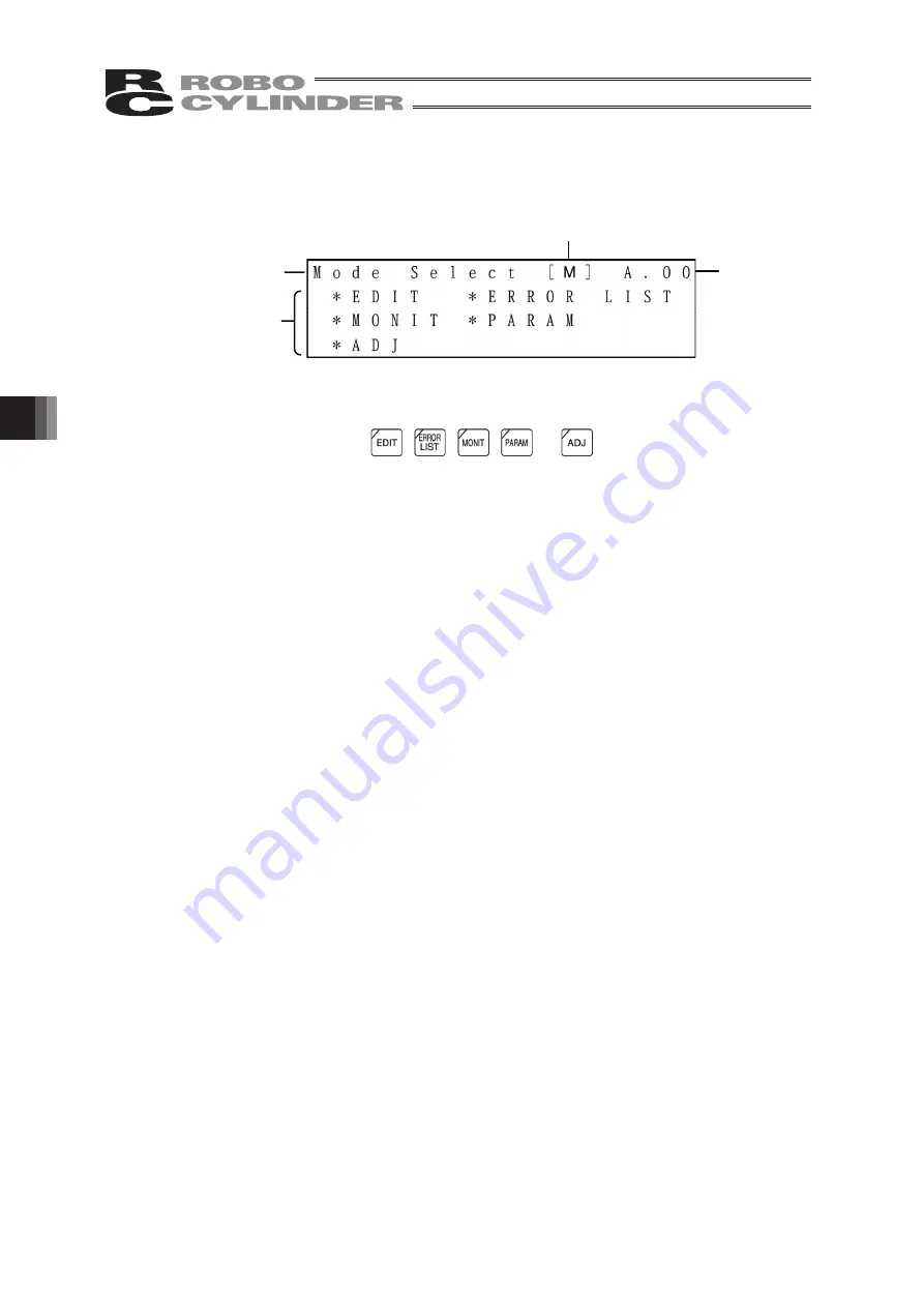
Mode Selection Screen
For the modes, select one of the 5 options as it appears on the above screen.
To select it, press one of the
,
,
,
or
keys.
The screen will move to the screen of the selected mode.
However, it cannot move to any mode with the key LED out.
Category of Modes
(1) * EDIT
Positioner (PCON-PL/PO, ACON-PL/PO or SCON: Mode other than the
Pulse Train mode. ERC3: Mode other than the Pulse Train Mode)
Display and Edit function for positioner table
(Refer to 6.4 and 6.5)
Pulse Train (PCON-PL/PO, ACON-PL/PO or SCON: Pulse Train Mode.
ERC3: Pulse Train Mode) Jog Operation, Inching Operation
(Refer to 6.5.8)
(2) * MONIT
Controller status display (Refer to 6.6)
(3) * ERROR LIST
(4) * PARAM
Setting of axis zone signal output range and axis attributes (Refer to 6.8)
(5) * ADJ
Executing homing and axis number setting of controller series (Refer to 6.9)
Protocol type display
Board type display
Selected
controller
axis number
Screen Display
Listing of modes
Alarm content detailed display (Refer to 6.7)
Name
Summary of Contents for Robo Cylinder CON-T
Page 1: ...Teaching Pendant Instruction Manual Tenth Edition CON T CON TG CON TGS IAI Corporation ...
Page 2: ......
Page 4: ......
Page 8: ......
Page 18: ... ...
Page 24: ...14 4 Functions and Specications of Teaching Pendant 4 2 External View External Dimensions ...
Page 97: ...87 6 Operation Mode Flow Chart Examples of PCON CY Controller On following page ...
Page 98: ...88 6 Operation Mode Flow Chart From previous page On following page ...
Page 99: ...89 6 Operation Mode Flow Chart From previous page On following page ...
Page 100: ...90 6 Operation Mode Flow Chart From previous page ...
Page 117: ......


