38
6.
Operation:
Mode
Flow
Chart
39
(3) Vel:
• Input the speed at which the actuator will be moved, in [mm/sec].
The initial value will depend on the actuator type.
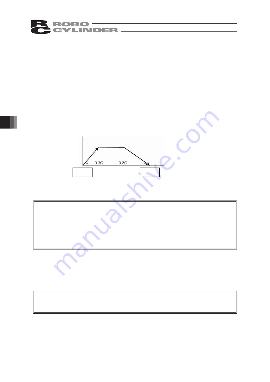
(4) Acc/Dcc: • Input the acceleration/deceleration at which the actuator will be moved, in [G].
Basically, use acceleration/deceleration within the catalog rated value range.
The input range allows larger value input than the catalog rated values, on the
assumption that the tact time will be reduced if the transfer mass is
significantly
smaller than the rated value.
Make the numeric value smaller if transfer work vibrates and causes
trouble during acceleration/deceleration.
The acceleration will become sudden if the numeric value is made larger and it
will become gradual if the numeric value is made smaller.
Caution:
Enter appropriate values for Vel and Acc/Dec in such a way as to prevent excessive
impact or vibration from being applied to the actuator in consideration of
the installation conditions and the shape of transferred work by referring to the
“List of Actuator
Specifications”
in the Appendix.
Increasing such values largely relates to the transfer mass and the actuator
characteristics vary depending on the model, consult IAI regarding the
input-limiting values.
(5) Push:
• Select the
“positioning operation” or “push operation”.
The default value is
“0.”
0:
Normal positioning operation
Other than 0: Indicates the current-limiting value and indicates the push operation.
Caution:
In the case of PCON, ACON, SCON or ERC2 there are cases where the
input value to
“Push”
may be rounded off to a multiple of the minimum resolution
of the controller (during data acquisition from the controller).
Acceleration
Speed
Start
position
Deceleration
Target
position
Time
(Note) For SCON-CA, PCON-CA and ERC3, an alarm will be displayed if the
set value is lower than the minimum velocity.
(Note) For SCON-CA, PCON-CA and ERC3, an alarm will be displayed if the
set value exceeds the rated acceleration/deceleration.
Summary of Contents for Robo Cylinder CON-T
Page 1: ...Teaching Pendant Instruction Manual Tenth Edition CON T CON TG CON TGS IAI Corporation ...
Page 2: ......
Page 4: ......
Page 8: ......
Page 18: ... ...
Page 24: ...14 4 Functions and Specications of Teaching Pendant 4 2 External View External Dimensions ...
Page 97: ...87 6 Operation Mode Flow Chart Examples of PCON CY Controller On following page ...
Page 98: ...88 6 Operation Mode Flow Chart From previous page On following page ...
Page 99: ...89 6 Operation Mode Flow Chart From previous page On following page ...
Page 100: ...90 6 Operation Mode Flow Chart From previous page ...
Page 117: ......


