38
39
6.
Operation:
Mode
Flow
Chart
(6) LoTh:
• In the case of the PCON-CF/CFA controller, the load output signal (PIO) will
be output if the command torque exceeds the value (%) set to “LoTh.”
Set the test range with “Zone+/-”.
Use it to judge whether push has been performed normally.
* For details, refer to the Operating Manual of PCON-CF/CFA Controller.
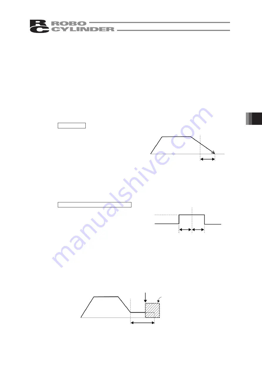
(7) Range:
• The “positioning operation” and “push operation” have different meanings.
Positioning operation:
It defines the distance to the target position from a position at which
the position complete signal turns ON.
The default value is 0.1 mm.
Standard type
However, it defines the width of the position complete signal to turn ON for
the 3-point type of PCON-C/CG/CF, PCON-CA, ACON-C/CG, ACON-CA, DCON-CA,
SCON and ERC3 PIO Converter and the proximity switch type of PCON-CY and
ACON-CY.
3-point type and proximity switch type
Push operation:
It defines the maximum push amount from the target position in
the push operation.
Set the positioning width in such a way as to prevent positioning
completion before the actuator contacts work by considering
mechanical variations of work.
Since increasing the positioning width value
hastens the next sequence operation, it
becomes a factor for tact time reduction.
Set the optimum value by considering the
balance of the entire equipment.
Timing of position
complete signal turning ON
Positioning width
Target
position
Positioning width
Target
position
Position complete signal
ON
OFF
Position at which the position complete
signal turns ON when the actuator contacts
work and push completion is judged
Target
position
Positioning width
(Maximum push amount)
Work
(Note) For PCON-CA, ACON-CA, DCON-CA and ERC3, a smaller value than
the minimum positioning width cannot be set.
Summary of Contents for Robo Cylinder CON-T
Page 1: ...Teaching Pendant Instruction Manual Tenth Edition CON T CON TG CON TGS IAI Corporation ...
Page 2: ......
Page 4: ......
Page 8: ......
Page 18: ... ...
Page 24: ...14 4 Functions and Specications of Teaching Pendant 4 2 External View External Dimensions ...
Page 97: ...87 6 Operation Mode Flow Chart Examples of PCON CY Controller On following page ...
Page 98: ...88 6 Operation Mode Flow Chart From previous page On following page ...
Page 99: ...89 6 Operation Mode Flow Chart From previous page On following page ...
Page 100: ...90 6 Operation Mode Flow Chart From previous page ...
Page 117: ......


