40
6.
Operation:
Mode
Flow
Chart
41
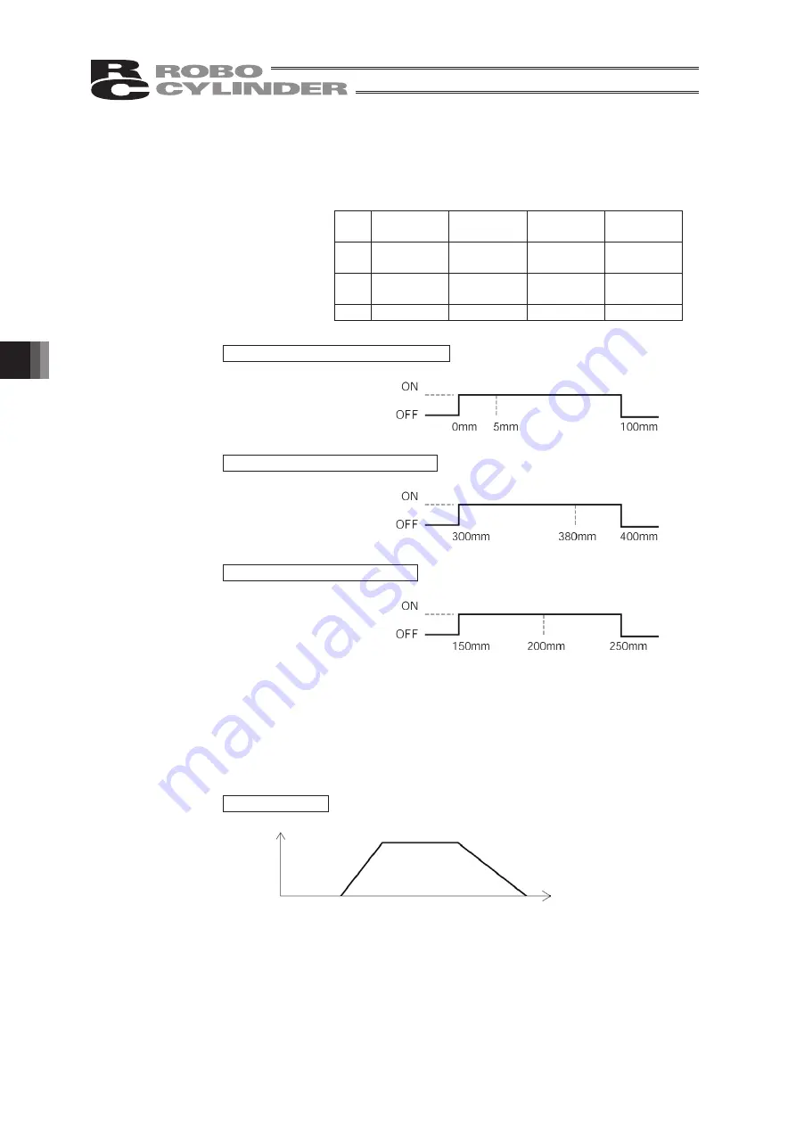
• It defines the zone where the zone output signal of the standard type turns
ON.
Individual setting is available for each target position to give flexibility.
No.
Position
[mm]
Zone+
[mm]
Zone-
[mm]
Comment
0
5.00
100.00
0.00
Backward
end
1
380.00
400.00
300.00
Forward
end
2
200.00
250.00
150.00
Midpoint
Movement command to backward end
Movement command to forward end
Movement command to midpoint
• It defines the acceleration/deceleration characteristics.
The default value is 0.
0: Trapezoid pattern
1: S-shaped motion
2: First-order delay filter
Trapezoid pattern
* Set the acceleration and deceleration in the “Acc” and “Dcl” fields of
the position table.
[Setting example]
Home
Zone output signal
Backward
end
+ side limit
Zone output signal
Forward
end
Zone output signal
Midpoint
Speed
Acceleration
Deceleration
Time
(8) Zone +/-:
(9) Acc/Dcl Mode:
Summary of Contents for Robo Cylinder CON-T
Page 1: ...Teaching Pendant Instruction Manual Tenth Edition CON T CON TG CON TGS IAI Corporation ...
Page 2: ......
Page 4: ......
Page 8: ......
Page 18: ... ...
Page 24: ...14 4 Functions and Specications of Teaching Pendant 4 2 External View External Dimensions ...
Page 97: ...87 6 Operation Mode Flow Chart Examples of PCON CY Controller On following page ...
Page 98: ...88 6 Operation Mode Flow Chart From previous page On following page ...
Page 99: ...89 6 Operation Mode Flow Chart From previous page On following page ...
Page 100: ...90 6 Operation Mode Flow Chart From previous page ...
Page 117: ......


