42
6.
Operation:
Mode
Flow
Chart
43
(11) Stop Mode:
• It defines the power saving method on standby after completion of
positioning to the target position set in the “Position” field of the position
number.
0: Invalid power saving method * The default setting is 0 (invalid).
1: Auto servo OFF method. Delay time defined with the parameter No. 36
2: Auto servo OFF method. Delay time defined with the parameter No. 37
3: Auto servo OFF method. Delay time defined with the parameter No. 38
4: Full servo control method
Full servo control method
The holding current can be reduced by servo-controlling the pulse motor.
The degree of reduction varies depending on the actuator model, load condition, etc.,
but the holding current decreases approximately by a factor of 2 to 4.
No displacement occurs since this method maintains the servo ON status.
The actual holding current can be checked on the monitoring screen of PC-compatible
software.
Auto servo OFF method
When a given length of time has elapsed after completion of positioning, the servo OFF
status is automatically entered.
(Since the holding current does not flow, the power consumption can be saved by the
same amount.)
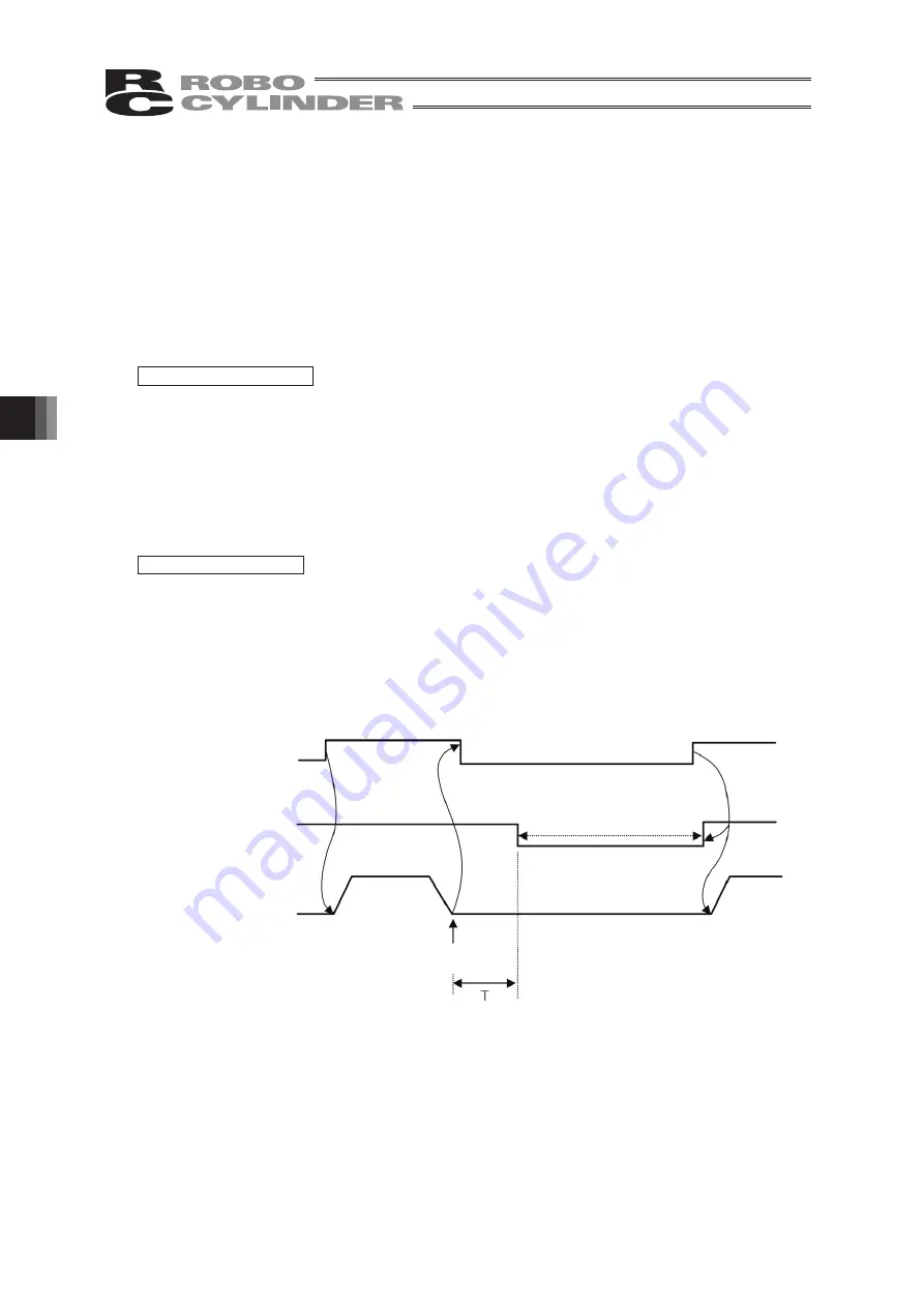
When a movement command is subsequently given fr om PLC, the status returns to
the servo ON and the actuator starts to move.
Movement
command
Servo status
Actuator
movement
Servo ON status
Auto servo OFF
(Green LED flashing)
Target position
T: Delay time (sec) until the servo
OFF status is entered after
completion of positioning
It is set with the parameter.
Summary of Contents for Robo Cylinder CON-T
Page 1: ...Teaching Pendant Instruction Manual Tenth Edition CON T CON TG CON TGS IAI Corporation ...
Page 2: ......
Page 4: ......
Page 8: ......
Page 18: ... ...
Page 24: ...14 4 Functions and Specications of Teaching Pendant 4 2 External View External Dimensions ...
Page 97: ...87 6 Operation Mode Flow Chart Examples of PCON CY Controller On following page ...
Page 98: ...88 6 Operation Mode Flow Chart From previous page On following page ...
Page 99: ...89 6 Operation Mode Flow Chart From previous page On following page ...
Page 100: ...90 6 Operation Mode Flow Chart From previous page ...
Page 117: ......


