2
6.
Operation:
Mode
Flow
Chart
3
Operation
Screen
Reference
7.
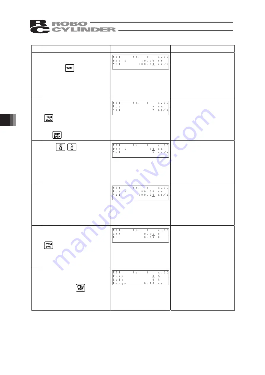
Press the Return key.
Press the
key.
(The cursor will automatically
move to the next [No. 1]
position.)
At the left, the user parameter
is used as it is.
The screen will change to the
screen of Position No. 1 for
Acc and Dcc.
8.
Change the display to the
screen for Pos and Vel with the
key.
Move the cursor to “Pos” with
the
key.
9.
Input
here, and then
press the Return key.
10.
The cursor will automatically
move to “Vel.”
11. Change the display to the
screen for Acc and Dcc with the
key.
The screen will change.
12. Change the display to the
screen for Push, LoTh and
Range with the
key.
The screen will change.
Summary of Contents for Robo Cylinder CON-T
Page 1: ...Teaching Pendant Instruction Manual Tenth Edition CON T CON TG CON TGS IAI Corporation ...
Page 2: ......
Page 4: ......
Page 8: ......
Page 18: ... ...
Page 24: ...14 4 Functions and Specications of Teaching Pendant 4 2 External View External Dimensions ...
Page 97: ...87 6 Operation Mode Flow Chart Examples of PCON CY Controller On following page ...
Page 98: ...88 6 Operation Mode Flow Chart From previous page On following page ...
Page 99: ...89 6 Operation Mode Flow Chart From previous page On following page ...
Page 100: ...90 6 Operation Mode Flow Chart From previous page ...
Page 117: ......


