76
77
6.
Operation:
Mode
Flow
Chart
6.6 Monitor
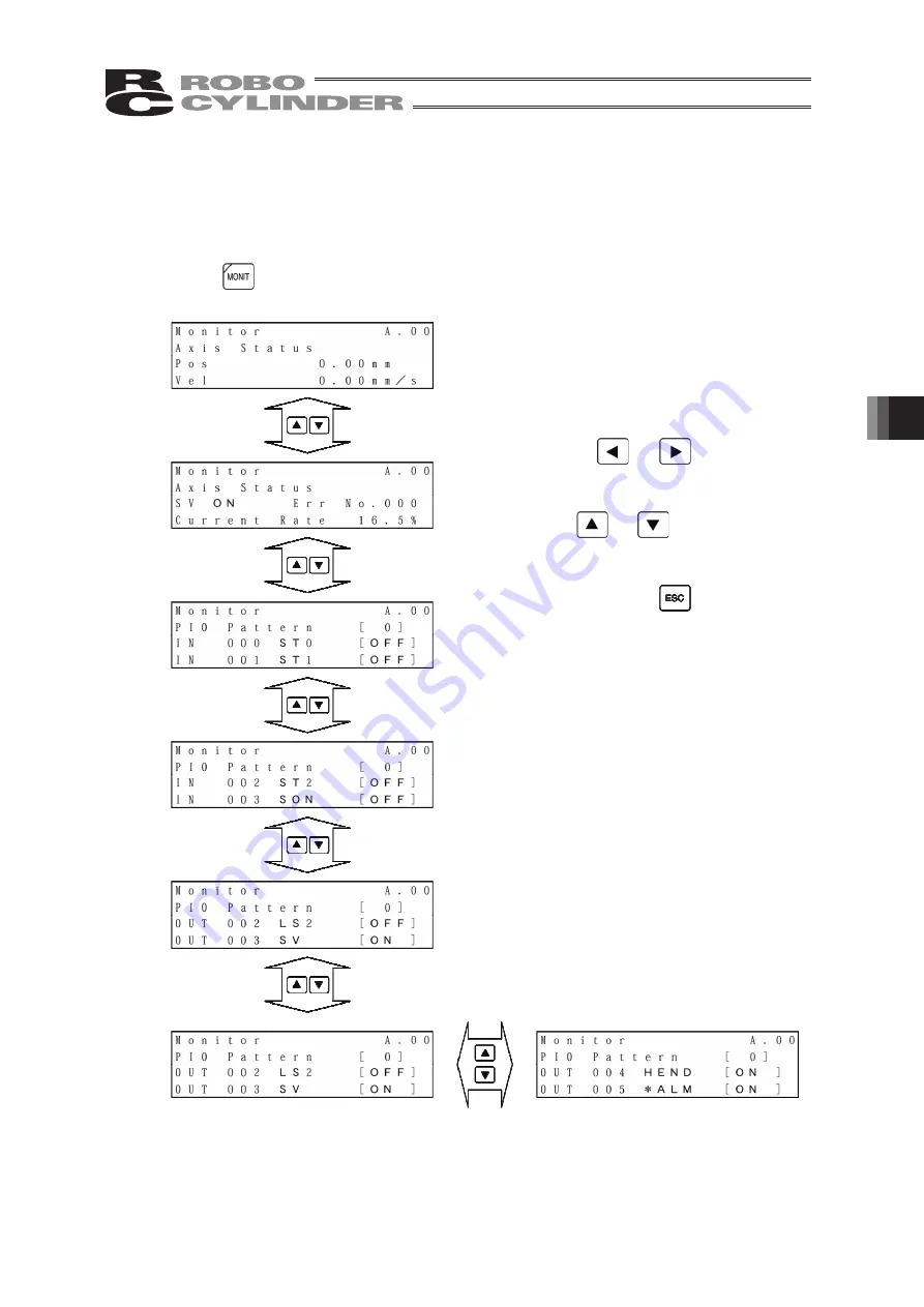
The I/O status and current position will be displayed for all the controllers connected on the
serial communication line.
Press the
key.
After this, the screen will change to the special
input port or version display screen.
The figure at the left shows an example of the
PCON-CY controller.
* The display contents vary depending on the
controller or controller’s I/O pattern. For details,
refer to the operating manual of each controller.
If you press the
or
key, the axis
to monitor can be changed.
If you press the
or
key, the screen
will change.
To end monitoring, press the
key.
Summary of Contents for Robo Cylinder CON-T
Page 1: ...Teaching Pendant Instruction Manual Tenth Edition CON T CON TG CON TGS IAI Corporation ...
Page 2: ......
Page 4: ......
Page 8: ......
Page 18: ... ...
Page 24: ...14 4 Functions and Specications of Teaching Pendant 4 2 External View External Dimensions ...
Page 97: ...87 6 Operation Mode Flow Chart Examples of PCON CY Controller On following page ...
Page 98: ...88 6 Operation Mode Flow Chart From previous page On following page ...
Page 99: ...89 6 Operation Mode Flow Chart From previous page On following page ...
Page 100: ...90 6 Operation Mode Flow Chart From previous page ...
Page 117: ......


