iAIRE
ION Kit I/O/M
iAIRE, LLC
11
Mount the wall plate first. Place the detector against the wall at the desired location. The wires must be able to pass through the notch
on the wall plate. Reference figure 1 for dimensions.
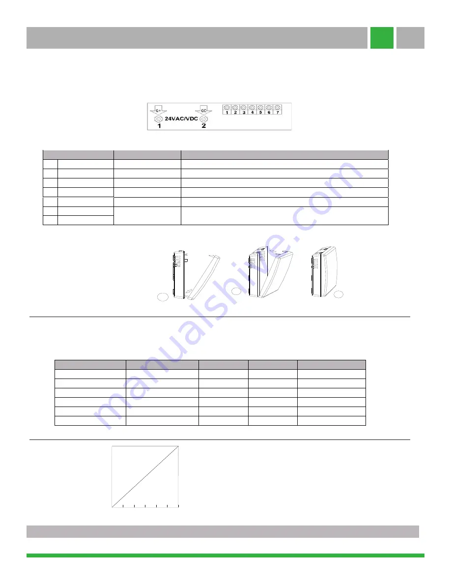
Connect wires to terminal strips, (see the label on the wall plate and fig.3). Make sure wiring connection is correct and secure.
The transmitter has been set at 0~10VDC analog output before leaving the factory. If you want to change the output voltage, please
operate as noted in the table below: Cut off power and simultaneously depress the 2 clips on either of the sides of the transmitter to
remove the faceplate from the wall plate. There are four jumpers on the top left of circuit (S1, S2, J1, J2) and choose a different output
voltage through disconnection or connection as noted in the table below.
Analog output and Corresponding VOC Values
Note:
When you test and install the transmitter, please take
notice that it should be placed perpendicular to the ground
and keep head-on. Because the air hole is at the bottom of
the product, incorrect placement can affect the test result.
Electrical Data
1
G+
Power (+)
24VAC/24VDC +
2
G0
Power ground (-)
24VAC/24VDC
3
OUT
Analog output (+)
0~10VDC (default)
4
B
RS485 interface
9600/14400/19200(default)/28800/38400bps (programmable selection),
15KV antistatic protection.
5
A
S2
S1
J1
J2
Analog Output
Upper two pins connection
Upper two pins connection
connection
Un-effective
4mA~20mA
Upper two pins connection
Upper two pins connection
disconnection
Un-effective
No analog output
Below two pins connection
Below two pins connection
connection
connection
1VDC~5VDC
Below two pins connection
Below two pins connection
connection
disconnection
2VDC~10VDC
Below two pins connection
Below two pins connection
disconnection
connection
0~5VDC
Below two pins connection
Below two pins connection
disconnection
disconnection
0~10VDC
Figure.3 connection
7
0~10VDC Analog Output
Indoor Air Quality
good
poor
SEN-0071
6
5
Connection Terminal Function
6
7
ON
OP
Alarm output
Alarm Common
0/2-10VDC
or 0/4-20mA
0V
10V
0ppm 5ppm 10ppm 15ppm 20ppm 25ppm 30ppm
Mount the wall plate first. Place the detector against the wall at the desired location. The wires must be able to pass through the notch
on the wall plate. Reference figure 1 for dimensions.
Connect wires to terminal strips, (see the label on the wall plate and fig.3). Make sure wiring connection is correct and secure.
Select the Voltage of Output
Follow the steps in figure 4 to close the cover.
Figure . 4 closing steps
Page
2
iAIRE | www.my
ultrapure
.com |
844-348-9168


