background image

iAIRE 

ION Kit I/O/M

iAIRE, LLC

5

The Ion Kit comes with ion block(s), ion mounting bracket(s), a VOC sensor and a terminal strip that provides 

feedback through a dry contact closure. When there are 4 or more blocks in a kit, 24V power supplies are 

included to provide enough power to the system.

The first step is to mount the ion generator(s). Reference the ION-0A*00 install sheet provided at the end of this 

document for more information about installing the individual ion generators.

Ion Generator(s)

ION Kit Installation

Ionization can only clean the air when the fan on the HVAC unit is running.  The thermostat fan setting should be 

put to “On” (not auto) to ensure the fan continually runs and that the air is constantly cleaned.  If this is not done, 

the air cleaning done by ionization will be lower than expected.

ION Kit Operational Notes

Once each ion generator is landed, the wires from each 

ion generator need to be run back and landed on the 

terminal strip. The Ion Kit gets power from the existing 

24V power in the HVAC unit if there are 3 or less ion 

generators. If there are 4 or more ion generators, 24V 

power supplies are provided and need to be installed.  

Once the ion generators, VOC sensor, terminal strip 

and power supplies are mounted, tie the feedback 

from the unit to the monitoring devices you are using to 

ensure that the ionization is always working. Reference 

wiring schematic provided on the next page.

If using multiple ion generators, tie the wires of

each generator together after mounting (if using the

mounting plate, mount the generators to the plate

and tie the wires of each generator together before

mounting each plate). Be sure to keep all wires away

from the generator tips, moving objects and areas that

may cause wires to be sucked into the blower.

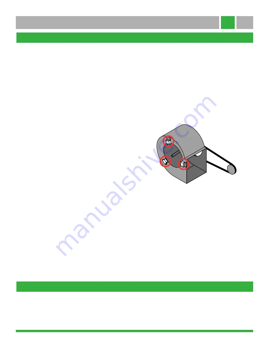
figure [1.3]

Wiring

Position the ion generator(s) perpendicular to the air stream by mounting them to the inlet of the supply fan on 

the opposite side of the drive shaft and belt. See figure [1.3] below. This may require the removal of the top panel 

on the RTU. If multiple blowers exist, evenly distribute the number of ion generators between them.

Summary of Contents for ION KIT Series

Page 1: ...ION XX KIT I O M Manual PD 04 20 2023 v 01 16 PN IOM 0022...

Page 2: ...it I O M 2 Table of Contents ION Kit Overview 3 Package Submittal 4 Installation and Operational Notes 5 Ion Install Kit Wiring 6 Ion Generator Submittal 8 Ion Generator Installation 9 SEN 0071 VOC Se...

Page 3: ...vironment size the Ion Kit to perform at 2500 CFM per block However if you are in a smoking or a fried food environment each ionization block will only do 1 250 CFM block Be sure to size your ionizati...

Page 4: ...re Ion devices UL 867 CSA C22 2 File 101141865COL 003 iAIRE LLC 2100 Consulate Drive Suite 102 Orlando FL 32837 www myultrapure com Toll Free 844 348 9168 SUB 0002 PD 04 20 2023 v 1 21 Part Ion Genera...

Page 5: ...p The Ion Kit gets power from the existing 24V power in the HVAC unit if there are 3 or less ion generators If there are 4 or more ion generators 24V power supplies are provided and need to be install...

Page 6: ...VAC 240VAC 480VAC BLK WHT RED ORG BLK RED F FI IG GU UR RE E 3 3 YEL BLUE COMMON 120VAC 208VAC 240VAC 480VAC BLK WHT RED ORG BLK RED YEL BLUE TRANSFORMER 2 2 TRANSFORMER 3 3 1 24VAC VDC 2 G 24VAC VDC...

Page 7: ...iAIRE ION Kit I O M iAIRE LLC 7 The following are reference product installation sheets...

Page 8: ...Homes Schools Animal Feeding and Processing Plants Shopping Malls Laboratories Veterinary Offices Restaurants and Food Preparation Areas Zoos Casinos Convention Centers and Arenas Jails Museums Health...

Page 9: ...urface to prevent arcing The ion air purifier has two mounting flanges with a hole to accommodate 1 8 self tapping sheet metal screws figure 1 1 With the provided metal screws mount the ion air purifi...

Page 10: ...in figure 2 Then slant the screwdriver and gently separate the cover from the wall plate by following steps 2 through 4 60 0 0 45 00 55 00 28 0 0 3 0 0 4 5 0 8 0 0 Figure 1 l SEN 0071 Indoor Air Qual...

Page 11: ...log output 0 10VDC default 4 B RS485 interface 9600 14400 19200 default 28800 38400bps programmable selection 15KV antistatic protection 5 A S2 S1 J1 J2 Analog Output Upper two pins connection Upper t...

Page 12: ...pm VOC measurement 10ppm 1st yellow light on when 10ppm VOC measurement 15ppm 1st and 2nd yellow lights on when 15ppm VOC measurement 20ppm 1st red light on when 20ppm VOC measurement 25ppm 1st and 2n...

Reviews: