background image


- 19 - 


Total Memory:


Displays the total memory available in the system.The choice: N/A. 


DE Adapters: The IDE adapters control the hard disk drive. Use a separate sub-menu to

I

 configure each 

ful, it 

ns NONE ! The choice: None, Auto, or Manual.


isplay your disk drive size. 


ng a value of 65535 means no hard disk. Min = 0, Max = 65535


dvan d BIOS Features


hard disk drive. 


IDE HDD Auto-Detection: 

Press <Enter> to auto-detect HDD on this channel. If detection is success

fills the remaining fields on this menu. Press Enter 


IDE Channel 0 Master/Slave, IDE Channel 2, 3 Master: 

Selecting 'manual' lets you set the remaining fields on 

this screen and select the type of fixed disk. "User Type" will let you select the number of cylinders, 

eads, etc., Note: PRECOMP=65535 mea

h


Access Mode: 

Choose the access mode for this hard disk. The choice: CHS, LBA, Large, or Auto.


Capacity: 

Disk drive capacity (Approximated). Note that this size is usually slightly greater than the size of 

 formatted disk given by a disk checking program. Auto-D

a


The  following options are selectable only if the 'IDE Primary Master' item is set to 'Manual', and Access 

ode set to CHS.

m


ylinder:


Set the number of cylinders for this hard disk. Min = 0, Max = 65535

C


ead:


Set the number of read/write heads. Min = 0, Max = 255

H


Precomp:


Warning: Setti


Sector:  


Number of sector per track. Min = 0, Max = 255


Landing zone:


Set the Landing zone size. Min = 0, Max = 65535


A

ce


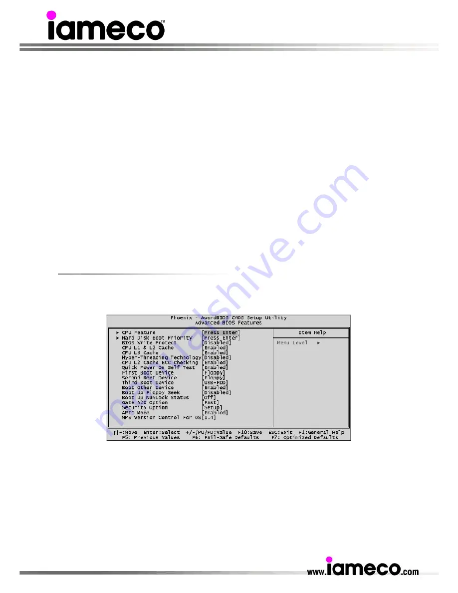
This section allows you to configure your system for basic operation. You have the opportunity to select 

the system's default speed, boot-up sequence, keyboard operation, shadowing, and security. 


CPU Feature: Press <Enter> to enter the sub-menu of detailed options.


 die throtting). 

atio of the throttled performance state that will be 


Delay prior to Thermal: This sets the delay time before the CPU enters auto thermal mode. The choice: 

one, 1/2/4/8/16/32/64Min.


N


Thermal Management: This item is select Thermal Management. Thermal Monitor 1 (On

Thermal Monitor 2 Ratio & VID transition). The Choice: Thermal Monitor 1 or Thermal Monitor 2.


M2 Bus Ratio: Represents the frequency (bus r

T
initiated when the on-diesensor gose from not hot to hot.  

ote:

 CPU support TM2, item appear.


N

Summary of Contents for ecoXPc

Page 1: ...1 ecoXPcInstallation guide Copyright 2007 includes setup service and troubleshooting information...

Page 2: ...Pro and the iameco logo are registered trademarks of Multimedia Computer Systems Ltd and its related entities All other trademarks are the property of their respective owners Alterations in respect of...

Page 3: ...Substances RoHS which is designed to ban the use of specific toxic substances The two directives are set to take effect in Jan 2007 and July 2006 respectively In addition the European commission propo...

Page 4: ...ed to provide environmental information on work processes loadings of substance costs of products evaluation of suppliers and accreditation of eco partners In addition EPS is equipped with the green p...

Page 5: ...es 1 ICE Heat Pipe 1 1 Adhesive 5 2 cable ties 12 1 Cable clip 4 1 Heatsink compound 10 Screws 11 Application CD Disk 2 Motherboard CD Drivers 32bits 64bits 7 1 XPc Extras CD 8 2 RAID Driver Floppy Di...

Page 6: ...nt out R L 13 Clear CMOS button A Wireless LAN perforation B Parallel port perforation Note Never force or over tighten any connectors If the connectors or ports don t join with reasonable ease they p...

Page 7: ...7 iameco XPc Intel Mainboard Mainboard illustration...

Page 8: ...ticularly Nylon Hold components by the edges to avoid touching the ICs on them Whenever you uninstall any component place it on a grounded antistatic pad or in the bag that came with the component Bef...

Page 9: ...Remove the ICE module from the chassis and put it aside Install the CPU Note This 775 pin socket is fragile and easily damaged Always use extreme care when installing a CPU and limit the number of ti...

Page 10: ...thermal compound on the CPU die Install the ICE Module Note Please do not use too much Heatsink compound 1 Place the ICE the module on top of the CPU and alig the spring loaded screws with the mainbo...

Page 11: ...e not supported 3 Only unbuffered without ECC DIMM are supported ote No jumper settings are required to configure memory The system BIOS utility automatically detects the memory settings Check the tot...

Page 12: ...screws from the side ssis 2 Place the rack in the cha 3 Refasten the rack on the ock and e 4 Place the power cables in the rack clip located underside of the rack mount then loosen the purse l separat...

Page 13: ...aser emanations harmful to human eye do not attempt to disassemble the unit Accessories Installation Install PCI AGP Card 1 A PCI AGP card will be used to demonstrate the installation procedure Unfast...

Page 14: ...factory default settings here is an easy to use Clear CMOS Button that allows users to reset BIOS e XPc and remove the power cord 2 Press the Clear CMOS Button by inserting a pointed object e g a pen...

Page 15: ...GLEDB 9 NC 5 Reset_SW 10 KEY Fan Connectors FAN1 FAN2 g may vary depending on the fan maker The mainboard provides two onboard 12V cooling fan power connectors to support CPU FAN1 System FAN2 cooling...

Page 16: ...D4 19 GND 7 PD5 20 GND 8 PD6 21 GND 9 PD7 22 GND 10 P_ ACK 23 GND 11 P_BUSY 24 GND 12 P_PE 25 GND 13 P_SLCT 26 KEY Startup errors The BIOS performs a variety of system tests at startup Serious problem...

Page 17: ...till wish to enter BIOS Setup restart the system and try again by turning the computer OFF and ON again or by pressing the RESET switch located at the computer s front panel You may also reboot by sim...

Page 18: ...Exit Without Saving Abandon all CMOS value changes and exit from setup Standard CMOS Features The items in the Standard CMOS Setup Menu are divided into several categories Each category includes none...

Page 19: ...k checking program Auto D a The following options are selectable only if the IDE Primary Master item is set to Manual and Access ode set to CHS m ylinder Set the number of cylinders for this hard disk...

Page 20: ...will be denied if the correct password is not entered ng and just press Enter it will disable security Once the security is to choose tiprocessor support version The choice d Note CPU support TM2 ite...

Page 21: ...dge Control A AGP Aperture Size MB Select the size of Accelerated Graphics Port AGP aperture The aperture is a portion of the PCI memory address range dedicated to graphics memory address space Host c...

Page 22: ...four IDE PIO Programmed Input Output fields let yo I 0 4 for each of the four IDE devices that the onboard IDE interface supports Modes 0 through 4 provide successively increased performance In Auto m...

Page 23: ...system enters the Suspend mode operating in a manner consistent with your own style of computer use ACPI Function This item allows you to enable disable the Advanced Configuration and Power Management...

Page 24: ...Up Control This item selects the PS2MS Power Up Control The choice Disabled Click Move Click Power Up by Alarm When set to Enabled the following three fields become available and you can set the nth...

Page 25: ...set Configuration Data Normally you leave this field Disabled Select Enabled to reset Extende System Configuration Data ESCD when you exit from Setup if you have installed a new dev oftware and the sy...

Page 26: ...nually modifying the CPU fan setting please make sure fan connectors are plug into the correct fan connector designations on the mainboard requency Voltage Control F CPU Clock Ratio This item allows y...

Page 27: ...with a message similar to Load Optimized Defaults Y N N Pressing Y loads the default values that are factory set for optimal system performance Set Password This item is to set a supervisor password...

Page 28: ...n is poor or there s a lot of dust where humidity is high or where the XPc may come into contact with oil or steam and do not place the XPc where the power cord is subject to damage The vents and othe...

Page 29: ...em Doing so may c time Do not pull the plug out by the wi to handle any cables Do not attempt to repair the power cord i iameco service representative N po ea C Other safety instructions Do not place...

Page 30: ...one Please contact your local authority for further details If your used electrical or electronic equipment has batteries or accumulators please dispose of these separately beforehand according to lo...

Page 31: ...rn r damage will no e accepted for return Returned items ition Please ensure that items ar insured for the full amount including e liable for any shipping charges the returned items ll original paperw...

Page 32: ...may use rebuilt reconditioned or new parts or components when repairing any product Upon request from iameco the nsumer must provide information to reasonably prove the date of purchase iameco reserve...

Page 33: ...n authorized representative of iameco of the possibility of any such damages This limitation applies whether damages are sought or a claim made under this limited warranty or as a tort claim including...

Page 34: ...obtained from the address www tcodevelopment com Eco Flower The European Union s eco labelling programme was launched throughout the European Community in 1993 to encourage the manufacture of less nv...

Page 35: ...certificate of Quality System Registration Number 3176 was issued on 2nd November 2006 and is valid ntil 1st November 2009 u ISO 14001 2004 The European Quality Assessment EQA granted iameco whose En...

Page 36: ...nable you to receive technical support and iameco newsletters periodically Failure to complete and submit this product registration form will not diminish your rights under iameco Standard Limited War...

Page 37: ...nfo micropro ie Contact Paul Maher Dublin 8 Ireland Tel 353 0 1 6745773 Woods Communications Unit L7 Ballymount Industrial Estate Dublin 12 Ireland Tel 353 0 1 4501898 Fax 353 0 1 4501946 Homepage www...

Reviews: