Page 11 2019-05-10
iancanada.mail@gmail.com
4. Why need to manage the end charge voltage
Disabling the charge current when it
’s closed to the fully charge voltage can prevent the battery cells from over
charge thus would be good for battery life time. The second reason is that some audio applications have sweet
voltage, program the end charge voltage can make it falling into the sweet spot each time when it
’s turned on.
Please keep in mind that when the charger goes to standby mode, the displayed battery voltage (discharge voltage
at standby) could be lower than the end charge voltage. The difference could be around 0.1V up to how much the
charging current it was or how many battery cells were installed. So, if you want the battery to be charged to 3.30V,
normally you will need to the end charge voltage to 3.39V or 3.40V.
5. How to solder battery holders or battery to the LifePO4 board
The LifePO4 MkIII PCB has double thickness copper layer (2oz) to get low ESR performance. However it will be
difficult to solder components to it than the normal PCBs. Have to use solder iron with 80W power or higher. Poor
soldering will cause malfunction or degrade the performance.
6. How to move the OLED board to front panel
(1). Break the OLED board from the power supply main PCB.
(2). Mound the OLED board to the front panel.
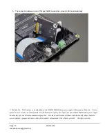
(3). Connect the OLED board with the main PCB through the supplied 10 pin FFC cable from J9 to J14.
Please see the picture “Connection between main PCB and external OLED board” for the orientation of cable.
Reversing the FFC/FPC cable can damage the processor chip,
so must be very careful.
Please make sure the DC power (J5 or J6) are fully
disconnected
before you move the OLED board.
7. How to have on/off button and power LED at front panel without removing OLED board
Connect the front panel on/off button and the power LED indicator to connector J11 by a jumper wire cable.
8. How to use multiple power supplies to get more voltage rails or extend the voltage range
(1). Link the power supplies together through the supplied bridge cable. The cable will be connected from J16 of
the master power supply to the J15 of the slave power supply, and so on.
(2). It is recommended to use separate DC input for each power supply. However, you can also share one DC input
with all power supplies through input terminal J6, but have to make sure the DC adapter can deliver enough
current.
(3). Since all pure battery outputs are galvanic isolated, you can connect different voltage rails in serial to extend
the voltage range.
(4). Can also work with later on ultra capacitor power supply in the same way.
9. How to replace fuse
Voltage rail J1, J2, J3 and J4 equipped with fuses for over current protection. You need to confirm whether they are
blown if there is no output. To replace a fuse, you will need:
(1). Lift one of the fuse terminals up by a needle. And then pick up it by a tweezers.

