background image

2

DISCLAIMER

1. Please use the original power supply, we cannot be held 

responsible for any problems or failures caused by any third party 

adapters.

2. Users may use music videos, images and software provided 

by third parties, but we cannot be held responsible for copyright 

issues or software failures.

3. If the product failure, we will strictly abide by the warranty terms, 

but we will not be held responsible for any property damage or 

financial loss that may be caused during use.

4. The equipment comes with built-in software at the factory, 

which can be used after the actual test. However, it will not affect 

the machine in any way if it is removed or not when looking for 

compatibility or other issues. Please note that it is not a product 

quality issue.

5. The company reserves the right to make improvements to its 

products and product specifications and designs are subject to 

change without notice! Please refer to the actual product.

Summary of Contents for QII-11515

Page 1: ...Please read carefully before using your equipment and store this manual for future reference Por favor l alo cuidadosamente antes de usar su equipo y gu rdelo para uso de futuras consultas USERMANUAL...

Page 2: ......

Page 3: ...n which the product was purchased if any term here is held to be invalid or unenforceable such term in so far as it is invalid or unenforceable shall be given no effect and deemed to be excluded witho...

Page 4: ...ms but we will not be held responsible for any property damage or financial loss that may be caused during use 4 The equipment comes with built in software at the factory which can be used after the a...

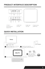
Page 5: ...3 PRODUCT INTERFACE DESCRIPTION QUICK INSTALLATION...

Page 6: ...the lower memory slot Remove the old memory module Gently unfold the metal retaining clips on each end of the memory slot to allow the module to pop out of the slot C Hold the module by its edges and...

Page 7: ...connector with a screwdriver counterclockwise shown in Figure 3 align the notch on the bottom of the new M 2 SSD with the tab on the connector then insert the bottom edge of the M 2 SSD into the conne...

Page 8: ...orresponding screw holes on the back of the mini pc as shown in Figure 6 2 Using the four small black screws included in the box attach the VESA bracket to the back of the monitor or TV as shown in Fi...

Page 9: ...the device frequently for a short period of time It is recommended that the interval between two boots should be at least 10 seconds preferably no less than 60 seconds 5 Pay attention to moisture keep...

Page 10: ...pr el producto si alguno de los t rminos en este documento se considera inv lido o inaplicable dicho t rmino en la medida en que sea inv lido o inaplicable no tendr efecto y se considerar excluido sin...

Page 11: ...s terminos de la garantia pero no nos responsabilizaremos de los dahos materiales ni de las perdidas economicas que puedan producirse durante su uso 4 EI equipo viene con un software incorporado de fa...

Page 12: ...10 DESCRIPCION DE LA INTERFAZ DEL PRODUCTO INSTALACION RAPIDA...

Page 13: ...ar un modulo de memoria que cumpla los siguientes requisites DDR4 2133 2400 3200MHz SO DIMM Nota Si tiene intencion de instalar solo un modulo de memoria instalelo en la ranura de memoria inferior Fig...

Page 14: ...los clips esten bien colocados SUSTITUYA O INSTALE EL SSD M 2 LA INSTALACION DE UN NUEVO SSD REQUIERE LA REINSTALACION DEL SISTEMA Retire la memoria SSD preinstalada si la hay del conector con un dest...

Page 15: ...parte posterior del mini pc como se muestra en la Figura 6 2 Con los cuatro tornillos negros pequehos incluidos en la caja fije el soporte VESA a la parte posterior del monitor o del televisor como s...

Page 16: ...con frecuencia durante un corto periodo de tiempo Se recomienda que el intervalo entre dos arranques sea de al menos 10 segundos prefer blemente no menos de 60 segundos 5 Preste atencion a la humedad...

Page 17: ......

Page 18: ......

Page 19: ......

Page 20: ......

Reviews: