7
3-- Operation
Viewing Page
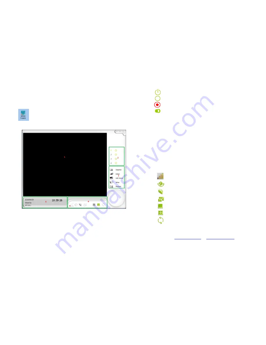
Insert the USB Receiver to one USB port of PC and double-click
on the desktop, the viewer screen will display as shown below
Main Screen
then turn on the camera.
1.
Monitoring Screen:
This will display the camera’s view.
Depending on the configuration, you can have different type of viewing
methods on this screen.
2.
Channel Status:
This will display the status of each individual
camera.
:
This icon indicates that the camera is monitoring
:
This icon indicates that the camera is in standby
mode
:
This icon indicates that the camera is recording
:
This icon indicates that the camera’s audio is enabled
3.
Option Menu:
This area allows you to do the following:
Snapshot:
Built-in snapshot function allows user to capture
images they would like
Detect:
Controls the view to go into detection mode or standby
mode
Web Server:
Enables web server mode for remote viewer
Setup:
This system built-in web interface offers more advanced
settings. On the viewing page, click the SETUP icon to enter
server settings page. It is a toggle button to switch between config
and view pages.
Playback
: Enters the playback mode to view recorded videos
4.
Camera/Screen Control:
This area controls the following:
:
Displays the signal strength of wireless cameras
:
Cruise camera to let it automatically move on its own
:
Opens the snapshot folders to view captured pictures
:
Adjusts the screen size on the monitoring screen
:
Displays one channel on the monitoring screen
:
Displays multiple channels on the monitoring screen
:
Cycles the camera to see all area
Copy Right
©
IA Technologies 02/23/2011
Webpage :
www.iat101.com
;
www.ia-tecs.com


