background image


Manual ibaFOB-SD


10 

Issue 1.3 


ibaPDA-Request-SD (former name Symbolic Request): 
Max. 4 boards with up to 50 µP connections (32 analog plus 32 digital signals 
each – a maximum of 1600 analog plus 1600 digital signals per card, depending 
on ibaPDA-V6 license); 
supports the ibaPDA-Technostring (a non-structured ASCII string) via the SD link. 


Bi-directional SD/TDC-Lite connection:(4 cards with up to 512 + 512 input values 
and 256 + 256 output values) for the ibaLogic Soft-PLC; 
supports the non-structured ASCII string via the SD link 


Important note 

It is 

not allowed

 to mix an ibaFOB-SD with an old ibaFOB SD x/2 (ISA) within one PC. 

To run the ibaFOB-SD the software versions ibaPDA V4.33 or ibaLogic V3.73 or higher 
are required. 


5.4 

Remarks concerning SIMADYN-D  

The coupling partner on the SIMADYN-D side can be CS12, CS13 und CS14 boards. 
The boards only differ in the amount of links supported by the cards (1, 4 or 8). If in the 
following text the CS14 is referred to the meaning is valid for CS12 and CS13 too.  

The CS14 is the coupling partner in the master rack. The max 8 slaves are connected 
via their CS22 cards or the ibaFOB-SD card. The physical connection is bi-directional 
fiber optic links in a start topology.  

The communication RAM is located within the CS14. Via this memory the slaves may 
communicate with the master and/or other slaves.  

The ibaPDA PC with his ibaFOB-SD card acts like a SIMADYN-D slave rack. 

This topology enables the ibaFOB-SD to communicate in theory with every processor 
in one of the connected racks (max 7) or the master rack. This would be up to 
64 CPUs. 

In reality the amount of connectable CPUs per ibaFOB-SD is limited to max. 50.  

5.5 

Remarks concerning CP53M0 

The board is available in Simatic TDC (D7-SYS V7.1 or higher). 

The board can be configured as master or slave. In master mode one port can be used 
for connection to ibaPDA/ibaLogic with ibaFOB-SD card. The other port provides for 
connection to a slave rack. The slave rack can be either SIMADYN D with CS22-board 
or SIMATIC TDC with CP53-board (slave mode). When operated in slave mode the 2

nd


port cannot be used. 


Summary of Contents for FOB-SD

Page 1: ...ibaFOB SD Manual Issue 1 3 3 ibaFOB SD Interface Board for Simadyn D Manual Issue 1 3 ...

Page 2: ... is not guaranteed However the information in this publication is updated regularly Required corrections are contained in the following regulations or can be downloaded on the Internet The current version is available for download on our web site http www iba ag com Protection note Windows is a label and registered trademark of the Microsoft Corporation Other pro duct and company names mentioned i...

Page 3: ...P53M0 10 5 6 Remarks on the measurement principle 12 5 7 Front view 13 5 8 Plug and socket connections 13 5 9 Indicators 14 5 9 1 Device LEDs 14 5 9 2 7 Segment display 14 5 9 3 Fiber optic interface 14 6 Mounting and dismounting 15 6 1 Safety information 15 6 2 Mounting 15 6 3 Dismounting 16 7 Software configuration in ibaPDA V6 17 8 Diagnosis in ibaPDA V6 18 8 1 General card diagnosis 18 8 1 1 T...

Page 4: ...ng 22 8 1 9 Tab Memory view 22 9 Synchronization of more than one iba PCI card 23 9 1 Important information 23 9 2 Procedure 23 10 Technical data 24 10 1 Main data 24 10 2 Performance of the ibaFOB SD card data load 25 11 Support and Contact 27 ...

Page 5: ... as professional if he she is capable of assessing safety and recognizing possible consequences and risks on the basis of his her spe cialist training knowledge and experience and knowledge of the standard regulations 1 2 Notations In this manual the following notations are used Action Notation Menu command Menu Logic diagram Call of menu command Step 1 Step 2 Step 3 Step x Example Select menu Log...

Page 6: ...the system or machine to be controlled there is a risk of death or severe injury The non observance of this safety information may result in a potential risk of death or severe injury The non observance of this safety information may result in a potential risk of injury or material damage Note A note indicates special requirements or actions to be observed Important information Information that a ...

Page 7: ...dows 7 ibaPDA V6 6 24 0 ibaPDA Version 4 33 with PCI support or higher ibaLogic V3 73 or higher ibaAnalyzer Version 3 0 or higher for data analysis 3 Safety information Please consider the following safety advises To prevent electrical shock during installation or uninstallation of the device disconnect the power supply from the computer before opening This board contains components which can be d...

Page 8: ... 1 3 4 Scope of delivery The following components are included with the delivery ibaFOB SD card Manual Synchronization cable sync cable For more accessories not included in the scope of delivery please refer to www iba ag com ...

Page 9: ...cess Firmware upgrade in the PC via PCI bus without de installing the card 3 LEDs for each channel indicating CPU life counter green optical transmission status orange and processor error red 7 segment display for board ID indication of sync master board and external or internal synchronization No Jumpers or DIL switches all parameters are software controlled the switch on top of the board is for ...

Page 10: ...eferred to the meaning is valid for CS12 and CS13 too The CS14 is the coupling partner in the master rack The max 8 slaves are connected via their CS22 cards or the ibaFOB SD card The physical connection is bi directional fiber optic links in a start topology The communication RAM is located within the CS14 Via this memory the slaves may communicate with the master and or other slaves The ibaPDA P...

Page 11: ...ibaFOB SD Manual Figure 1 Example of configuration with ibaPDA Issue 1 3 11 ...

Page 12: ...pret the SD address book and communicate with the SD in a way that any inter nal variable of any processor may be requested from the PLC To do that for every SD CPU two function blocks must be included in the CFC STRUC plan of the SD system These FBs support overload protection to avoid high system loads by ibaPDA SD TDC Lite All measuring values are pre programmed and a fixed part of the logic pl...

Page 13: ...7 Front view 1 7 segment display 2 Status LEDs 3 FO connector Receiver 4 FO connector Transmitter Figure 2 Front view 5 8 Plug and socket connections 1 Sync connector blue Figure 3 Plug and socket connections Issue 1 3 13 ...

Page 14: ...ted or sen ding device Err red On Off Internal error on controller link Normal state after resolution of error LED automatically resets 5 9 2 7 Segment display The 7 segment display shows the following information Horizontal line After System switch on until ibaPDA ibaLogic has initialized the board Board ID ranging from 0 to 3 After board was initialized The decimal dot ON Board is dedicated to b...

Page 15: ... advantage of the plug and play function be sure that ibaPDA V6 re spectively ibaLogic V4 has been installed before inserting the card Otherwise Win dows will not recognize the card 1 Shut down the PC 2 Switch off the power supply of the PC 3 Unplug the mains power line 4 Open the PC so you can reach the PCI slots 5 Take the card carefully out of the package 6 Grab the card at the front plate and ...

Page 16: ... of the PC 3 Unplug the mains power line 4 Open the PC so you can reach the PCI slots 5 Release the fixing screw 6 Unplug the card carefully out of the slot Store the card in an appropriate con tainer 7 Close the PC 8 Plug in the power line 9 Switch on the power supply of the PC 10 Start the PC ...

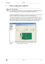
Page 17: ...ed in the dongle the card should be available in the I O manager s signal tree as a data interface If you click on the interface icon in the tree you will get a simplified image of the card and essential information in the right part of the dialog Here you should set the re quired interrupt mode of the card and check the option In use in order to reserve the card for use by ibaPDA V6 only and not ...

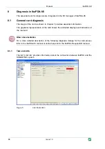
Page 18: ...on The graphical representation of the card shows the animated displays and indicators of the real card Other documentation For a more detailed description of the following diagnosis dialogs for the card please refer to the ibaPDA V6 manual or online help and to the ibaPDA Request SD manual 8 1 1 Tab Link info The tab Link info provides information about the connection between ibaPDA and the SIMAD...

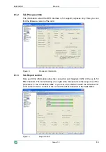
Page 19: ...8 1 3 Tab Report control Here you ll find information about the connection and telegram traffic of the up to 50 PDA channels The bit numbering 0 on right side corresponds to the sequence of the processors in the connection table If you move the slider beneath the bitmasks PN short name and error number of the current PN will be indicated in the fields below Figure 7 Report control Issue 1 3 19 ...

Page 20: ...ll find information about the command and acknowledge handshake during telegram traffic of the up to 50 PDA channels Figure 8 Command Acknowledge 8 1 5 Tab Data control Here you ll get information about the data traffic of the up to 50 PDA channels Figure 9 Data control ...

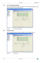
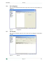
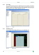
Page 21: ...ou find information about the CS14 report area where the connected BGTs are registered Figure 10 Configuration 8 1 7 Tab Channels Here you get information about the CS14 board and the configured communication channels Figure 11 Channels Issue 1 3 21 ...

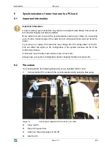
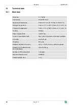
Page 22: ...vides a statistical log of all SD accesses Primarily this feature has been added as a helper for the software development and optimization But a user may use the information as well for a better configuration of the SD Figure 12 Timing 8 1 9 Tab Memory view This is a display of the 256 kByte DPR memory on the ibaFOB SD card Figure 13 Memory view ...

Page 23: ...nplug PCI cards this may change the PCI configuration of the PC This can affect the signal or I O configuration of the system because the ID of the boards may change In that case move the fiber optic cables to the correct card Always save your system configuration before changing hardware components 9 2 Procedure You should perform the following steps after you ve installed the PCI card 1 Connect ...

Page 24: ... 70 C Transport Temperature From 13 F to 158 F from 25 C to 70 C Cooling Passive Power Supply SLM via PCI bus Current consumption SLM Max 950 mA without connected modules FO cable Coupling 62 5 125 µm ST Lean Distance between 2 devices Up to 1 312 ft 400 m without repeater Weight incl Packaging and Documentation 0 44 lb 200 g Number of SD connections 1 duplex Data transmission rate 96 Mbit s Faste...

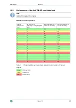
Page 25: ... efficiency without Techno string Measured efficiency with Techno string 1 2 100 100 1 3 90 50 1 4 50 50 2 4 100 100 2 5 100 100 2 6 100 100 2 7 99 55 2 8 50 50 3 8 100 100 3 10 100 100 3 11 99 50 3 12 50 50 4 12 100 100 4 14 100 100 4 15 100 95 4 16 50 50 Table 1 Processing efficiency depending on sample time and number of channels Legend Green FOB load is OK Yellow Critical load Red FOB overload...

Page 26: ...ation between sample time and number of channels TS Technostring Reading help example At a sample time of 8 ms ibaPDA it s possible to process up to 30 channels with Technostring and 31 channels without Technostring at an accept able efficiency ...

Page 27: ...specify the serial number iba S N of the product Contact Headquarters iba AG Koenigswarterstr 44 90762 Fuerth Germany Phone 49 911 97282 0 Fax 49 911 97282 33 E Mail iba iba ag com Contact Mr Harald Opel Regional and Worldwide For contact data of your regional iba office or representative please refer to our web site www iba ag com Issue 1 3 27 ...

Reviews: