ibaBM-SLM Manual
3.
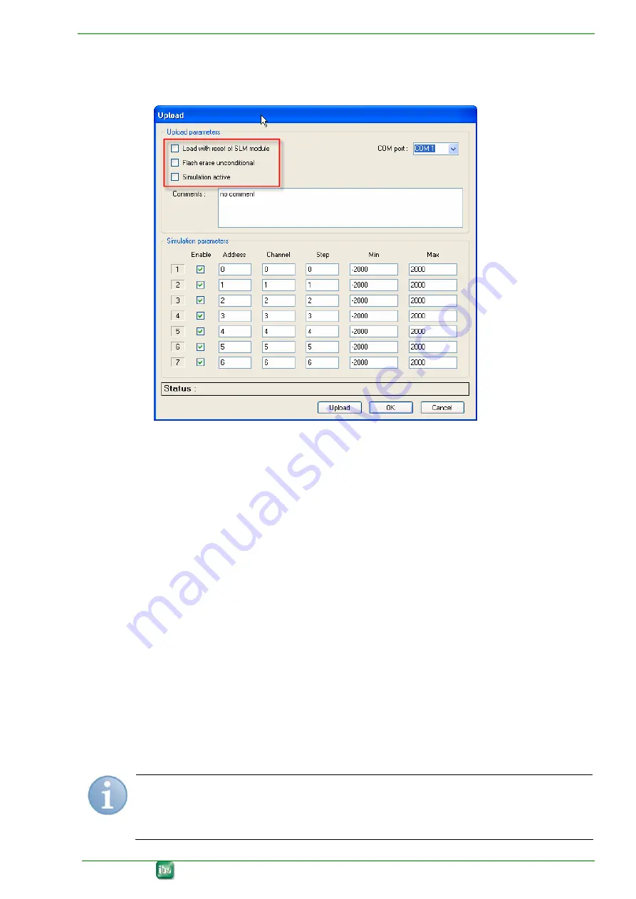
Then define the conditions, how the device should upload the parameters from
ibaPDA or if you want to work with simulated data.
Working with simulated data:
You can specify, how many simulated parameters (up to 7 are possible) the pa-
rameter set should contain.
You can change the values for each simulated parameter.
4.
Finally click on <Upload>.
The parameter set (real or simulated) will be uploaded into the device.
10.2.2
Reference to simulated parameters (simulation mode)
In simulation mode, a bus cycle of 1.6 ms is simulated, where up to 7 independent saw
tooth signals can be defined in DINT format. They can be released individually. Their
shape can be modified and each signal can be assigned to an individual virtual SI-
MOLINK address/channel.
Address
: address of the participant (0 to 200)
Channel
: channel number (0 to 7)
Step
: increment (+) or decrement (-) by which the signal should change for each bus
cycle
Min./Max.:
lower/upper limit of the saw tooth signal
Note
A blinking LED “Link” (yellow) shows the simulation mode.
The device remains in simulation mode until configured otherwise.
Issue 2.0
23


