Page 18
Manual
ibaFOB-4i-X
8.3
Front Side Elements
8.3.1
Status-LEDs
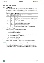
Run, Link and Error LEDs indicate the operational state of the ibaFOB channels. The fol-
lowing table describes the states in which you may find the LEDs and their respective
meanings. When switching on power all LEDs are on for a few seconds to prove their
proper function.
LED
Status
Description
Run
(green)
Flashing
OFF
/
ON
power is on and the channel is functioning properly
controller stopped
Link
(yellow)
ON
OFF
receiving / sending telegrams on this channel with 3.3 or 5 Mbit/s
no telegrams received; fiber optics not connected, 32 Mbit/s or sending
device off
Error
(red)
ON
OFF
internal error in controller link
normal state; after resolution of error, LED automatically resets
Rate
(white)
ON
Flashing
OFF
Transmission with 32 Mbit/s active (X-mode)
Set to X-mode but no telegrams received.
Transmission with 3.3 Mbit/s (F-mode) or 5.0 Mbit/s (M-mode)
8.3.2
7-Segment Display
The 7-segment display shows the following information
Board-ID (ranging from 0...7) - after board was initialized; when board is not initial-
ized a horizontal line is displayed.
The decimal point in the display indicates whether the board is dedicated to be...
an internal interrupt master (dot is on) or
an external interrupt master (dot is blinking) or
an interrupt slave (dot is off).
8.3.3
Fiber Optic Interface of ibaFOB-4i-X
The ibaFOB-4i-X provides four ST type jacks (grey) for the fiber optic receivers.
If the card was configured for external synchronization, e. g. for operation with an
ibaBM-SLM, the first (top) input channel needs to be connected with the external
device for proper function (otherwise the whole PC process will be stopped).
The external sync configuration channel will be indicated by a blinking dot in the 7-
segment display so that the correct data input can be identified easily (F-mode only).
iba AG 2012


