


16
IP417 U
ser’s Manual
2.4.4
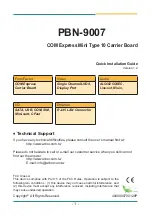
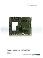
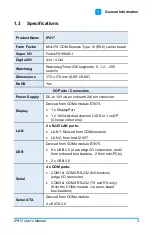
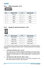
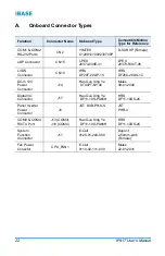
GPIO Connector (J17)
1
2
9
10
Pin
Signal Name
Pin
Signal Name
1
Ground
2
+3V
3
GPO3
4
GPO1
5
GPO2
6
GPO0
7
GPI3
8
GPI1
9
GPI2
10
GPI0
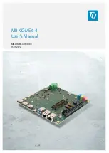
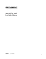
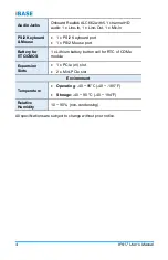
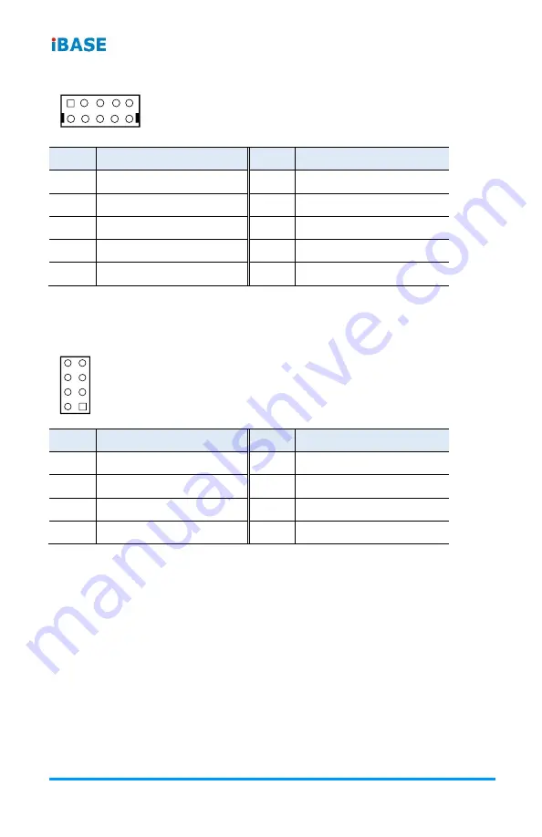
2.4.5
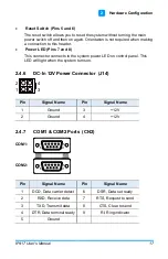
System Function Connector (J11)
1
2
8
7
Pin
Signal Name
Pin
Signal Name
1
Power BTN-
2
Power BTN+
3
HDD LED+
4
HDD LED-
5
Reset BTN-
6
Reset BTN+
7
Power LED+
8
Power LED-
J11 is used for system indicators to provide light indication of computer activities
and switches to change the computer status. It provides interfaces for the following
functions.
•
ATX Power ON Switch (Pins 1 and 2)
The 2 pins make an “ATX Power Supply On/Off Switch” for the system that
connects to the power switch on the case. When pressed, the power switch
will force the system to power on. When pressed again, it will power off the
system.
•
Hard Disk Drive LED Connector (Pins 3 and 4)
This connector connects to the hard drive activity LED on control panel. This
LED will flash when the HDD is being accessed.
Summary of Contents for IP417
Page 1: ...IP417 Mini ITX COM Express Type 10 R3 0 Carrier Board User s Manual Version 1 0 July 2019...
Page 8: ...viii IP417 User s Manual This page is intentionally left blank...
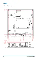
Page 14: ...6 IP417 User s Manual 1 5 Dimensions...
Page 28: ...20 IP417 User s Manual This page is intentionally left blank...