


Hardware Configuration
UPC-7210 Series User Manual
21
2
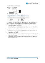
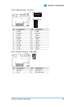
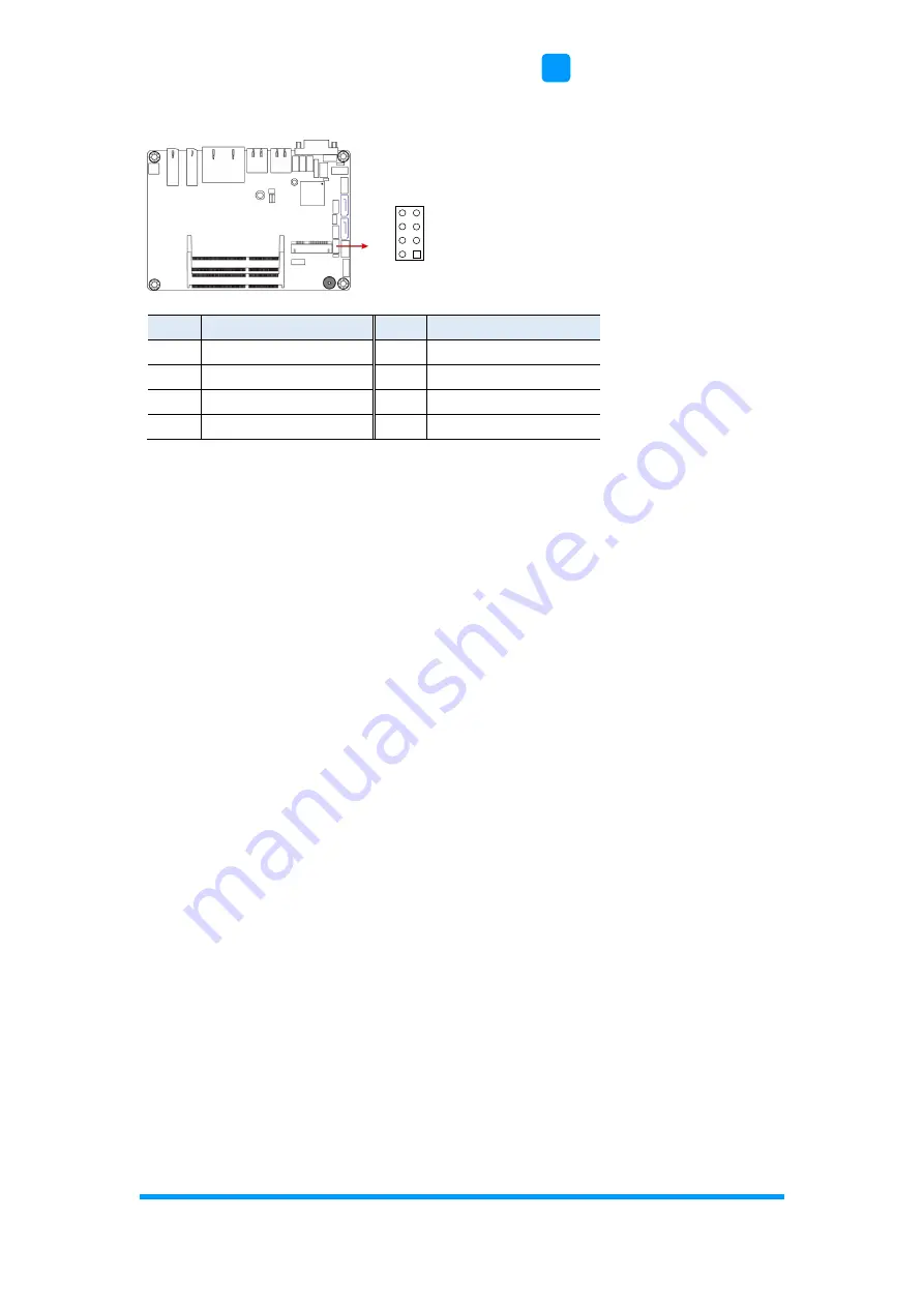
2.10.4 Front Panel Connector (J6)
Pin
Assignment
Pin
Assignment
1
Ground
2
PWR_BTN
3
3.3V
4
HDD Active
5
Ground
6
Reset
7
+5V
8
Ground
J6 is utilized for system indicators to provide light indication of the computer activities and
switches to change the computer status. It provides interfaces for the following functions.
•
ATX Power ON Switch (Pins 1 and 2)
The 2 pins makes
an “ATX Power Supply On/Off Switch” for the system that connects to
the power switch on the case. When pressed, the power switch will force the system to
power on. When pressed again, it will power off the system.
•
Hard Disk Drive LED Connector (Pins 3 and 4)
This connector connects to the hard drive activity LED on control panel. This LED will
flash when the HDD is being accessed.
•
Reset Switch (Pins 5 and 6)
The reset switch allows you to reset the system without turning the main power switch off
and then on again. Orientation is not required when making a connection to this header.
•
Power LED: Pins 7 and 8
This connector connects to the system power LED on control panel. This LED will light
when the system turns on.
1
2
8
7


