10
Check that
the control unit is connected as per instructions on page 9.
Input voltage 230-240 V +/-15%, 50/60 Hz.
Check that
the input signal is 0-10 V.
Check that
rotation monitor and cleaning function are connected.
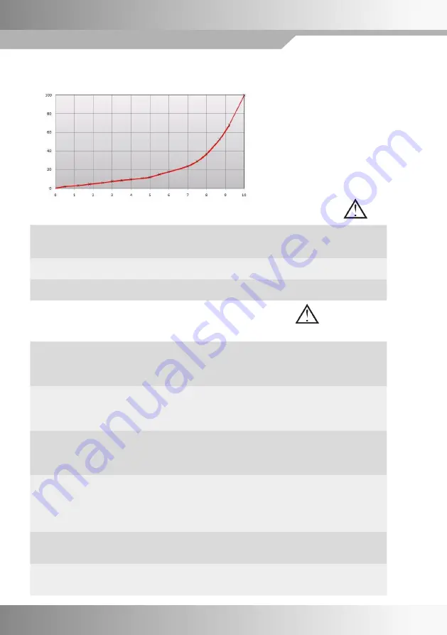
INPUT SIGNALS/ROTATION SPEED
The input signal is directly proportional
to the efficiency of the wheel, which
means that input signal and rotation
speed are as per adjoining diagram.
CHECKS BEFORE SWITCHING ON THE CONTROL UNIT
Check that
the motor rotates in the right direction in relation to the wheel's direction
of rotation.
In the event of a fault, switch two phases to the motor.
Adjustment of max.
speed
Set the DIP switch to "High speed" in the ON position.
Adjust "Max. speed" so that the wheel rotates at 10-12 rpm (or as per
directions from wheel manufacturer).
Checking minimum
speed
Set the DIP switch to "Low speed" in the ON position.
Check that the wheel starts.
The minimum speed is preset.
Checking the cleaning
function
Switch off the voltage.
Make sure that the "Cleaning" DIP switch is set to ON, and that the input
signal is disconnected.
After switching on the voltage the wheel rotates for 20 seconds at 12 rpm.
Checking the rotation
monitor
The yellow "Rotation" light diode should flash when the magnet passes
the magnetic sensor, whatever the DIP switch position.
Finish by
having the control unit drive the wheel at maximum and minimum
rotation speed and checking that the wheel speed is correct.
PUTTING THE EQUIPMENT INTO OPERATION
Should be done in sequence
11
Input signal 0-10 V
Input signal - rotation speed
Rotation speed [%]


