background image

INSTALLATION AND OPERATION INSTRUCTIONS

1-24

SL 10-85 G3,  SL 14-115 G3,  SL 20-160 G3, SL 30-199 G3 MODULATING GAS BOILERS

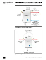
The SL series modulating boilers are designed to supply three different heating loads with 
temperatures within the range 34°F to 180°F - to meet three separately piped loads. Use 
closely spaced tees to connect each pumped “load” (e.g. DHW, baseboards or radiant 
floor) to the primary loop, or employ the use of a hydraulic separator to isolate the boiler 
loop from the system and pipe the system from the secondary side of the separator. Two-
load systems may be piped with a variant of parallel piping commonly used, including our 
unique dual side piping configuration.
Ensure that the pump is rated for the design circulating water temperatures; some pumps 
have a minimum water temperature rating above the low temperature potential of the 
boiler. Following installation, confirm the actual performance by measuring Δ°T (under high 
and low flow conditions)

.

A variety of application drawings showing basic design options are available from the IBC 
web site at:  www.ibcboiler.com

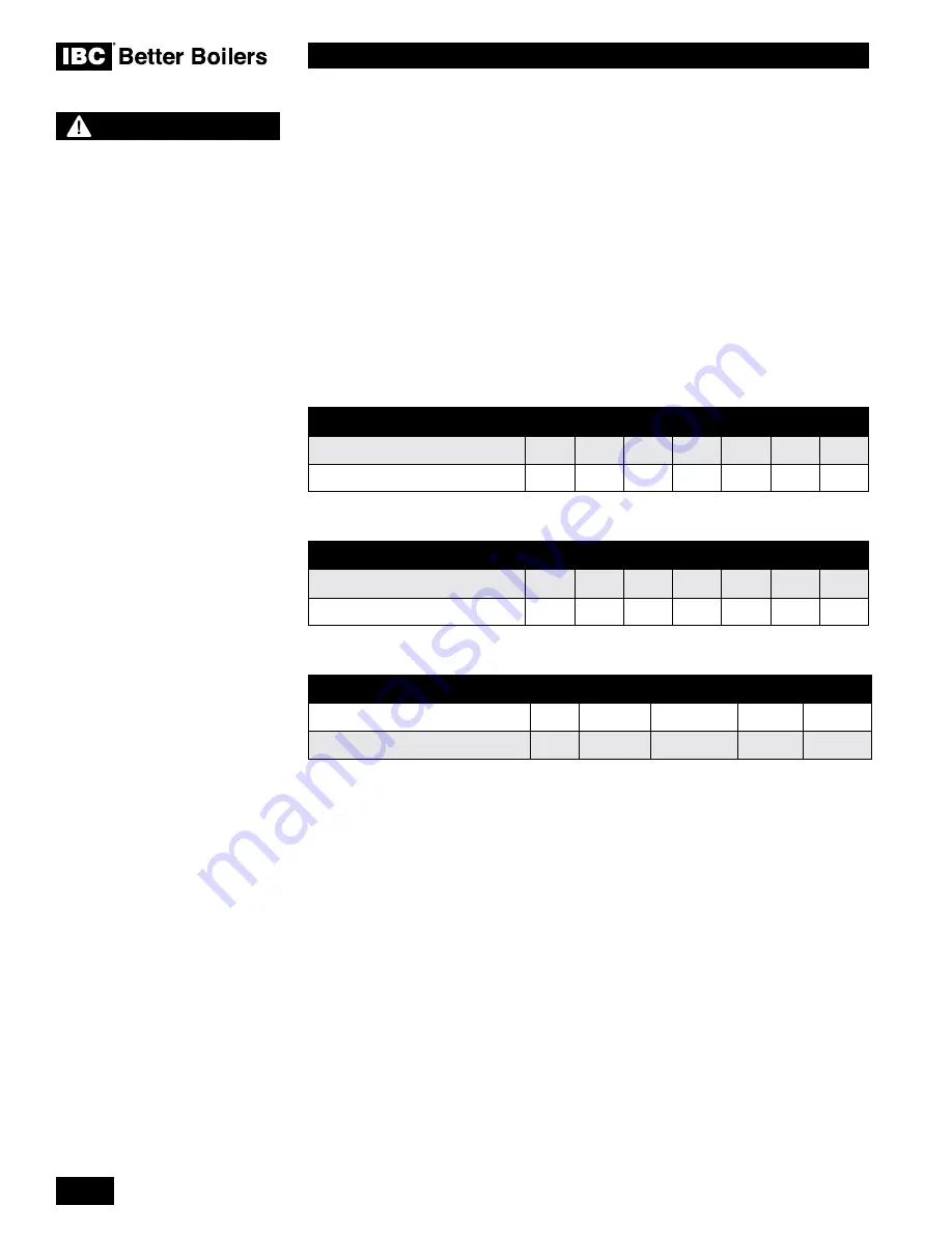
BOILER HEAD LOSS

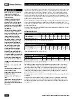
BOILER HEAD LOSS SL 10-85 G3, SL 14-115 G3

Flow rate (gpm)

2

4

6

8

10

12

 14

Head loss @ flow (ft wc)

0.5’

1.5’

2.5’

3.0’

4.0’

4.5’

6.0’

Table 5A: Boiler Head Loss -


SL 10-85 G3

/

SL 14-115 G3

BOILER HEAD LOSS SL 20-160 G3

Flow rate (gpm)

4

6

8

10

12

14

 16

Head loss @ flow (ft wc)

0.5’

1.0’

1.5’

2.0’

3.0’

4.0’

5.0’

Table 5B: Boiler Head Loss - SL 20-160 G3

BOILER HEAD LOSS SL 30-199 G3

Flow rate (gpm)

6

10

15

20

22

Head loss @ flow (ft wc)

2’

3.5’

5.5’

8’

13’

Table 5C: Boiler Head Loss - SL 30-199 G3

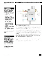
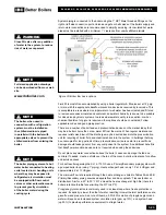
We recommend water flow after burner shutdown to utilize legacy heat – this is due to 
the mass of the heat exchanger plus its water volume. Default software values will run 
the boiler’s primary pump for up to 15 minutes (900 seconds) after burner shutdown. 
Secondary pumps can be set to run up to 5 minutes after burner shutdown (for the last 
calling load). As shipped, the default software will run the Boiler pump for 5 minutes to 
place the legacy heat where it is useful. 
The primary pump must be under the control of the boiler to allow pump purge after burner 
shut-down.
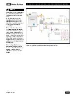
Schematics for several piping layouts are provided herein, and additional drawings are 
available at www.ibcboiler.com. Installers shall conform the piping design to one of the 
provided configurations to simplify the control application, promote good loads and flow 
management.

WARNING

Water quality has a significant 

impact on the lifetime and 

performance of an IBC Boiler 

heat exchanger.
Improperly prepared water in 

a heating circuit may cause 

damage to the heat exchanger 

through corrosion or fouling. 

Repeated or uncontrolled water 

fills will increase the potential 

for damage.

High levels of dissolved solids 

or minerals may precipitate 

out of the fluid onto the hottest 

part of the heat exchanger, 

impairing heat transfer and 

resulting in overheating and 

premature failure. The amount 

of solids that may form on the 

heat exchanger will depend 

on the degree of hardness and 

the total water volume in the 

system. A high water volume 

system with a low hardness 

count may cause as much 

damage as a system with less 

volume and higher hardness, so 

it is recommended to treat water 

so as to remove all dissolved 

solids. Other water chemistry 

allowable limits are as follows:

Acidity pH is to be between 6.6 

and 8.5
Chloride is to be less than 125 

mg/l

Iron is to be less than 0.5 mg/l
Cu less than 0.1 mg/l
Conductivity is to be less than 

400μS/cm (at 25°C)
Hardness is to be 7 Grains or 

less

IMPORTANT: Ensure that these 

limits are acceptable for the 

other water-side components in 

the system.

Summary of Contents for SL 20-160 G3

Page 1: ...quids or other combustible materials in the vicinity of this or any other appliance WHAT TO DO IF YOU SMELL GAS Do not try to light any appliance Do not touch any electrical switch do not use any phon...

Page 2: ...ants which in extreme cases might result in death HAZARDS PRECAUTIONS WARNING Points out a potentially hazardous situation which must be avoided to prevent serious injury or death CAUTION Points out a...

Page 3: ...ter content USG Litres 2 47 9 35 2 47 9 35 1 72 6 51 5 09 19 3 Maximum boiler flow rate USgpm 14 14 19 22 Minimum boiler flow rate USgpm 2 2 4 6 Maximum operating water pressure psig 30 30 30 30 Minim...

Page 4: ...INSTALLATION AND OPERATION INSTRUCTIONS 4 SL 10 85 G3 SL 14 115 G3 SL 20 160 G3 SL 30 199 G3 MODULATING GAS BOILERS THIS PAGE IS INTENTIONALLY LEFT BLANK...

Page 5: ...n 1 17 1 5 3 Condensate Trap Assembly cleaning procedure 1 18 1 5 4 Further installation details 1 18 1 6 WATER PIPING 1 20 1 6 1 General Piping Issues 1 20 1 6 2 Basic System Piping Arrangements 1 25...

Page 6: ...ce and Testing 4 3 4 2 GEOGRAPHY COMPONENTS 4 4 4 2 1 Fan and gas valve removal instructions 4 5 4 2 2 Fan and gas valve re assembly instructions 4 5 5 0 TROUBLESHOOTING 5 1 5 1 PRELIMINARY CHECKS 5 1...

Page 7: ...all building air intakes including those of neighboring properties In sealed combustion applications the exhaust outlet should be placed so as to reach 12 minimum above the down turned intake to avoid...

Page 8: ...INSTALLATION AND OPERATION INSTRUCTIONS 8 SL 10 85 G3 SL 14 115 G3 SL 20 160 G3 SL 30 199 G3 MODULATING GAS BOILERS THIS PAGE IS INTENTIONALLY LEFT BLANK...

Page 9: ...iping and electrical holes Refer to the applicable diagrams to help find a suitable location for the boiler See also Section 1 3 Location Figure 1 Dimensions Connections for SL SL 10 85 G3 SL 14 115 G...

Page 10: ...3 SL 14 115 G3 SL 20 160 G3 SL 30 199 G3 MODULATING GAS BOILERS Figure 2 Dimensions Connections for SL 20 160 G3 Front view side view top view and bottom view Figure 3 Dimensions Connections for SL 30...

Page 11: ...surrounding the boiler in a laundry room Similarly ensure any direct vent air source is not adjacent to a clothes dryer exhaust terminal Avoid agricultural applications where the boiler and or the int...

Page 12: ...exhaust plumes well away from all building air intakes including those of neighboring properties All venting must be installed in accordance with the requirements of the jurisdiction having authority...

Page 13: ...nd other spaces of the building Turn on clothes dryers and any appliance not connected to the common venting system Turn on any exhaust fans such as range hoods and bathroom exhausts so they will oper...

Page 14: ...ware to ensure that the maximum temperature of the PVC venting material is not exceeded PVC venting material shall be certified to Sch 40 ASTM D1785 or D2665 CPVC material shall be certified to Sch 40...

Page 15: ...exhaust during long burner runs at high fire in a 2 pipe can overcome gravity on 1 4 foot vent slope leaving a pool of condensate at the next upturned elbow Pooling can impair the achievement of full...

Page 16: ...a soap and water solution Installer must fill condensate trap prior to test Paint all joints with an approved leak test solution just as you would joints in a gas line and make sure there are no leaks...

Page 17: ...w the installation instructions supplied with the venting material manufacturer Care must be taken to install the termination kit a minimum horizontal distance of 10 305cm away from any portion of the...

Page 18: ...imum of 24 with the SL boilers to avoid damage to the structure Note Prohibited unless fully open on a minimum of two sides below the floor Vents must be installed such that flue gas does not discharg...

Page 19: ...to protect the wall Bird screen of 1 4 stainless steel or plastic mesh eg IPEX System 636 drain grate for CPVC systems is useful to guard against foreign objects CAUTION Vent termination clearances i...

Page 20: ...vent air connections fit Sched 40 two inch or three inch PVC CPVC pipe PPs pipe cannot be used with the SST The pipes must extend completely through the wall as shown in Figure 16 The SST is an exter...

Page 21: ...GAS BOILERS Figure 15 Allowed SST installation orientations Figure 18 Minimum separations for multiple vent installation horizontal orientation Figure 17 Minimum separation for multiple vent installat...

Page 22: ...lt NOTE Care must be taken when installing air intake piping to ensure that a trap is not formed in the piping so as to allow a build up of water and blockage of intake air Such blockage will result i...

Page 23: ...icularly so for horizontal runs follow local code 1 4 8 Indoor Air Combustion Air Intake An Indoor Combustion Air installation as described herein is one in which air for combustion is taken from the...

Page 24: ...n and written approval of the IBC Engineering Department 1 4 10 Closet Installations For installations in a confined space such as a closet ventilation openings may be needed through a door or wall to...

Page 25: ...ve Drain Hose G from the Trap Drain Outlet F Place the Vacuum breaker cap J over the Vacuum breaker opening and push firmly home Remove the Upper Compression Nut and Washer C and slide over the Boiler...

Page 26: ...components re fill trap and replace on boiler as described in the installation instructions above 1 5 4 Further installation details Condensate drain must be piped to within 1 of a drain or be connect...

Page 27: ...densates are to be discharged into building drain piping materials that are subject to corrosion a neutralization package must be used CAUTION When a condensate neutralization package is installed the...

Page 28: ...for maximum flexibility in multi load applications but piping loads in parallel is also encouraged in systems that only have two loads or when loads are operating simultaneously The extremely low pre...

Page 29: ...e is no possibility of installing an isolation valve between the pressure vessel and the relief valve CAUTION Installers should inquire of local water purveyors as to the suitability of their supply f...

Page 30: ...D OPERATION INSTRUCTIONS 1 22 SL 10 85 G3 SL 14 115 G3 SL 20 160 G3 SL 30 199 G3 MODULATING GAS BOILERS Figure 29 Relief piping with dual side connections Figure 28 Relief piping with single side pipi...

Page 31: ...s above the boiler Leaks can damage the fan and controls If needed create a shield over the top of the cover but allow clearance for airflow and service access For best results regarding the SL 14 115...

Page 32: ...software values will run the boiler s primary pump for up to 15 minutes 900 seconds after burner shutdown Secondary pumps can be set to run up to 5 minutes after burner shutdown for the last calling l...

Page 33: ...primary piping circuit and potentially lengthen the duration of the transition from hot to cool loads SL modulating series boilers can be connected directly to a floor of non oxygen barrier polybutyl...

Page 34: ...RUCTIONS 1 26 SL 10 85 G3 SL 14 115 G3 SL 20 160 G3 SL 30 199 G3 MODULATING GAS BOILERS Figure 33 Typical one temperature space heating piping concept Figure 32 One temperature space heating piping co...

Page 35: ...rder to ensure they are compatible Many air handlers fan coils for instance have a thermostat connection that will energize an internal relay to operate the air handler circulator and its fan on a cal...

Page 36: ...es to a successful installation There are many necessary components not shown and details such as thermal traps are left out so the drawings have greater clarity We require that our boilers be install...

Page 37: ...S BOILERS Parallel load piping Benefits and installation rules Compared with the Primary Secondary approach the design below saves one pump Lost is the simplicity of constant head and flow at the boil...

Page 38: ...wn pump as illustrated below This approach provides constant head and flow at each boiler regardless of flow variations in the main building loop Each boiler will control its own pump turning it off o...

Page 39: ...gth ft Schedule 40 steel NOTE It is essential to check gas supply pressure to each boiler with a manometer or other high quality precision measuring device Pressure should be monitored before firing t...

Page 40: ...d or the National Electrical Code ANS NFPA No 70 latest edition or the Canadian Electrical Code C22 1 Part 1 1 8 1 120 VAC Line Voltage Hook up Line voltage wiring is done within the field wiring box...

Page 41: ...es where the boiler has been repeatedly de powered wet The combined current of all pumps connected through the on board pump relays should not exceed 10 amps The control circuit board is protected usi...

Page 42: ...connection this is used for connecting multiple SL and or VFC modulating units for autonomous staging The bottom pair of contacts receives a 0 10VDC default or 4 20 mA signal from an external boiler c...

Page 43: ...G3 SL 14 115 G3 SL 20 160 G3 SL 30 199 G3 MODULATING GAS BOILERS SL 10 85 G3 SL 14 115 G3 SL 20 160 G3 SL 30 199 G3 MODULATING GAS BOILERS Figure 43 Electrical Wiring Connections full page ladder diag...

Page 44: ...INSTALLATION AND OPERATION INSTRUCTIONS 1 36 SL 10 85 G3 SL 14 115 G3 SL 20 160 G3 SL 30 199 G3 MODULATING GAS BOILERS THIS PAGE IS INTENTIONALLY LEFT BLANK...

Page 45: ...r a USB stick Setup configuration back up and cloning using an SD card or USB stick Superior warning messages while setting up the control Advanced Error messages with visual display on the Home Scree...

Page 46: ...reen title bar at the top and a border surrounding the active area At the bottom of the display there is space reserved for the boiler status bar Prior to any interaction with the touch screen the dis...

Page 47: ...3 1 STARTUP AND COMMISSIONING SL 10 85 G3 SL 14 115 G3 SL 20 160 G3 SL 30 199 G3 MODULATING GAS BOILERS 3 0 STARTUP COMMISSIONING 3 1 LIGHTING BOILER SHUTDOWN...

Page 48: ...ely outside the boiler case Ensure boiler has shut off and the appropriate Error information is displayed on the Touch Screen To restart boiler reset power or press Clear Errors in the Advanced Diagno...

Page 49: ...fine adjustment and may require several turns Note This screw has significant backlash When changing direction of turn it may take up to a full turn before any change is indicated on the analyzer rea...

Page 50: ...Fuel Conversion kits Fuel conversions must be carried out by a qualified technician 1 Ensure you are installing the correct fuel conversion kit for your boiler Compare the boiler model number with the...

Page 51: ...nent marker make an alignment mark between the lid gasket and heat exchanger Before removing the lid it is important to be positioned directly above it to ensure a straight up extraction Failing to do...

Page 52: ...unding temperature 3 Remove the 8 Torx screws around the fan coupler and lift off the fan coupler carefully Note The fan coupler seals against the heat exchanger lid with a high temperature silicone O...

Page 53: ...ect the burner gasket look for cracks deterioration or signs of gas bypass Replace if necessary 2 Place the heat exchanger lid on a flat surface and position the gasket on the lid aligning it with the...

Page 54: ...INSTALLATION AND OPERATION INSTRUCTIONS 3 8 SL 10 85 G3 SL 14 115 G3 SL 20 160 G3 SL 30 199 G3 MODULATING GAS BOILERS THIS PAGE IS INTENTIONALLY LEFT BLANK...

Page 55: ...if the burner requires cleaning every year In alternate years visually inspect the burner through the sight glass Ensure that the flame is stable and is without excessive fluttering Normal flame patte...

Page 56: ...ter connections are left in the closed position to minimize exposure to leaks and flooding 4 1 11 Freeze Protection Check the freeze protection Use only antifreeze made specifically for hydronic syste...

Page 57: ...ot completely seal and fluid continues to leak from the discharge pipe perform the test again to try and flush any debris that may be lodged in the valve If repeated tries fail to stop the leakage con...

Page 58: ...nitor 8 Air pressure switch behind bracket 14 Combustion Test Port 3 Site Glass 9 Touchscreen controller 15 Fan Coupler 4 Combustion Fan 10 Return Water Temperature Sensor 16 Return Water Pipe behind...

Page 59: ...tall the new gas valve with the gasket in position tighten the union nut to the inlet of the gas valve 4 2 2 Fan and gas valve re assembly instructions 1 Place the fan gasket on the outlet of the fan...

Page 60: ...INSTALLATION AND OPERATION INSTRUCTIONS 4 6 SL 10 85 G3 SL 14 115 G3 SL 20 160 G3 SL 30 199 G3 MODULATING GAS BOILERS THIS PAGE IS INTENTIONALLY LEFT BLANK...

Page 61: ...manual are a number of diagrams see Section 6 0 for use with troubleshooting including Electrical Wiring Diagrams Sequence of Operations Flowchart Boiler Component Layout Diagrams 5 1 PRELIMINARY CHE...

Page 62: ...n a resistance reading remove power to the boiler For the supply water and return water temperature sensors remove the wire leads by disconnecting their respective Molex connectors Place multi meter p...

Page 63: ...then crack the pressure relief valve The pressure displayed should reflect declining pressure If it remains fixed drain the boiler and replace the sensor or dislodge any blocking debris from the senso...

Page 64: ...is pressurized and that the air has been removed 1 On the touchscreen controller tap the Home screen 2 On the Main Menu tap the Diagnostics button 3 Tap the Advanced Diagnostics button 4 Tap the Clear...

Page 65: ...e boiler after a Hi Limit lockout Before you reset the boiler ensure that the boiler is pressurized and that the air has been removed 1 On the touchscreen controller tap the Home screen 2 On the Main...

Page 66: ...ing power to gas valve close gas supply then disconnect black electric housing from face of gas valve gently spread plastic tabs to open and look for 24vac voltage during an ignition cycle Replace mod...

Page 67: ...n acceptable range Potential flow or sensor failure Consult service technician Current outlet temperature exceeds operating limit Check water flow Defective or disconnected temperature sensor Check wi...

Page 68: ...S WHEN IGNITING Fluctuating gas pressure gas pressure too high too low Check CO2 level via analyzer Check for proper gas piping Check pressure with manometer during ignition BOILER WILL NOT ATTEMPT TO...

Page 69: ...etting with ammeter Air in system or marginal water flow Bleed purge system as required Confirm adequate pump size and temp rise in HX Slow combustion air blower Check that CO2 level is within specifi...

Page 70: ...across heat exchanger Poor gas air mixing Check CO2 level Defective thermostat Refer to manufacturer s instructions Obstruction in condensate drain Inspect and clean condensate drain Unit cycling on o...

Page 71: ...fety device and clear the error in the Advanced Diagnostics menu DHW TAKING TOO LONG TO HEAT Sensor may be under reading actual water temp Check sensor engagement note well is 15cm almost 6 inches dee...

Page 72: ...INSTALLATION AND OPERATION INSTRUCTIONS 5 12 SL 10 85 G3 SL 14 115 G3 SL 20 160 G3 SL 30 199 G3 MODULATING GAS BOILERS THIS PAGE IS INTENTIONALLY LEFT BLANK...

Page 73: ...6 1 DIAGRAMS SL 10 85 G3 SL 14 115 G3 SL 20 160 G3 SL 30 199 G3 MODULATING GAS BOILERS 6 0 DIAGRAMS This section includes Parts diagrams Wiring diagrams Sequence of operation...

Page 74: ...D OPERATION INSTRUCTIONS 6 2 SL 10 85 G3 SL 14 115 G3 SL 20 160 G3 SL 30 199 G3 MODULATING GAS BOILERS 6 1 PARTS DIAGRAMS Diagram 6 1 1 Boiler assembly parts SL 10 85 G3 SL 14 115 G3 Modulating Boiler...

Page 75: ...6 3 DIAGRAMS SL 10 85 G3 SL 14 115 G3 SL 20 160 G3 SL 30 199 G3 MODULATING GAS BOILERS...

Page 76: ...INSTALLATION AND OPERATION INSTRUCTIONS 6 4 SL 10 85 G3 SL 14 115 G3 SL 20 160 G3 SL 30 199 G3 MODULATING GAS BOILERS SL 20 160 G3 Modulating Boiler Parts assembly Diagram 6 1 2 Boiler assembly parts...

Page 77: ...6 5 DIAGRAMS SL 10 85 G3 SL 14 115 G3 SL 20 160 G3 SL 30 199 G3 MODULATING GAS BOILERS...

Page 78: ...INSTALLATION AND OPERATION INSTRUCTIONS 6 6 SL 10 85 G3 SL 14 115 G3 SL 20 160 G3 SL 30 199 G3 MODULATING GAS BOILERS SL 30 199 G3 Modulating Boiler Parts assembly Diagram 6 1 3 Boiler assembly parts...

Page 79: ...6 7 DIAGRAMS SL 10 85 G3 SL 14 115 G3 SL 20 160 G3 SL 30 199 G3 MODULATING GAS BOILERS...

Page 80: ...INSTALLATION AND OPERATION INSTRUCTIONS 6 8 SL 10 85 G3 SL 14 115 G3 SL 20 160 G3 SL 30 199 G3 MODULATING GAS BOILERS Diagram 6 2 1 Ladder wiring diagram 6 2 WIRING DIAGRAMS...

Page 81: ...n green green green black Upper Vessel High Limit Switch white yellow white red white white yellow brown black blue orange orange blue Inlet Water Pressure Sensor white white black yellow To Boiler Pu...

Page 82: ...INSTALLATION AND OPERATION INSTRUCTIONS 6 10 SL 10 85 G3 SL 14 115 G3 SL 20 160 G3 SL 30 199 G3 MODULATING GAS BOILERS 6 3 SEQUENCE OF OPERATION Diagram 6 3 Sequence of operation diagram...

Page 83: ...g Instructions Leak testing completed gas piping venting system Fan and combustion components System Cleaned and Flushed type of cleaner used ________________________________________________ System Fi...

Page 84: ...ration Load 2 _____________________________________________________________________________________________ Load Definition Load 3 _____________________________________________________________________...

Page 85: ...SERVICE RECORD DATE LICENSED CONTRACTOR DESCRIPTION OF WORK DONE...

Page 86: ...NOTES...

Page 87: ...NOTES...

Page 88: ...t system that serves the same function THIS OVERRIDE MUST NOT BE USED UNLESS AT LEAST ONE OF THE FOLLOWING CONDITIONS IS TRUE An external energy management system is installed that reduces the boiler...

Page 89: ...ures 33 and 34 Corrections to text Specifications table and part numbers R3 MAY 2017 Corrections to tables and part numbers R4 July 2017 Inclusion of information relating to the SL 30 199 G3 boiler R5...

Page 90: ...IBC Technologies Inc 8015 North Fraser Way Burnaby BC Canada V5J 5M8 Tel 604 877 0277 Fax 604 877 0295 Toll Free 1 844 432 8422 www ibcboiler com September 2017 IBC Technologies Inc 2017...

Reviews: