INSTALLATION AND OPERATION INSTRUCTIONS
1-20
SL 35-199, SL 45-260 MODULATING GAS BOILERS
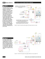
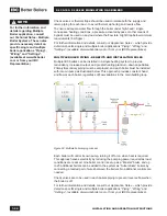
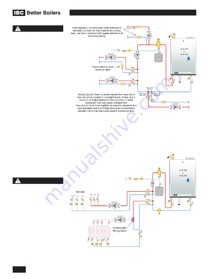
Figure 23: Basic Primary/Secondary piping with closely-spaced tees concept
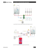
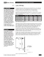
Figure 24: Important Primary/Secondary piping details with closely-spaced tees
NOTE
The piping drawings in this
manual are simple schematic
guides to a successful
installation. There are many
necessary components not
shown, and details such as
thermal traps are left out so
the drawings have greater
clarity. We require that
our boilers be installed by
licensed and experienced
trades people who are familiar
with the applicable local
and national codes. System
design is to be completed
by an experienced hydronic
designer or Engineer. It is
necessary to carefully read
and follow these installation
instructions along with the
application drawing that fits
your system.
NOTE
SL 35-199 / 45-260 boilers
are equipped with a factory
installed pressure sensor-
type Low Water Cut Off. The
minimum operating system
pressure allowable with this
is 4 psig. Check local codes
if a Low Water Cutoff Device
is required. If so, determine
if this device meets the local
codes.
Summary of Contents for SL 35-199
Page 71: ...SERVICE RECORD DATE LICENSED CONTRACTOR DESCRIPTION OF WORK DONE...
Page 72: ...NOTES...
Page 73: ...NOTES...

