1-23
INSTALLATION
SL 35-199, SL 45-260 MODULATING GAS BOILERS
The use of the multi-temperature modulating system is optimized when the need
to shutdown the boiler is reduced or eliminated during the transitional period.
System design enhancements: (a) keep a relatively low thermal mass in the
primary loop, and (b) incorporate a 3-way mixing valve on the “cool” load piping.
If the installation involves small loads, as in typical zoned baseboard heating
applications, use of a buffer tank is recommended. To aid in temperature
transition from hot to cool loads, a 3-way mixing valve can be placed at the
entrance to the cool load (this will also provide floor protection). This will permit
immediate circulation of mixed flow into the cool loop.
See separate publication
Application Notes for more detail (available at www.ibcboiler.com or from your
IBC Representative).
Always ensure that loads sensitive to high temperatures (e.g. radiant floor)
are protected using appropriate means such as a manual mixing valve, or an
aquastat (set to130°F, for example) wired to the boiler’s auxiliary interlocks.
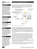
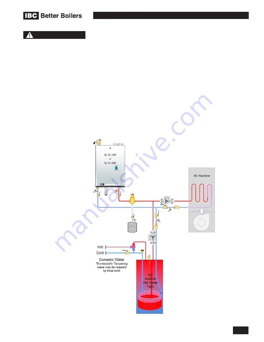
PARALLEL LOAD PIPING - BENEFITS AND INSTALLATION RULES
Compared with the Primary/Secondary approach, the design below saves one
pump. Lost is the simplicity of constant head and flow at the boiler.
NOTE
Load Combining is now
available to operate 2
compatible water temperature
loads at the same time.
When using the sequential
load feature of the IBC boiler,
attention must be paid to
the operation of system
components in order to
ensure they are compatible.
Many air handlers (fan
coils) for instance have a
thermostat connection that
will energize an internal relay
to operate the air handler
circulator and its fan on
a call for heat. This may
result in operation of these
components when other
loads are running at a higher
priority, resulting in cold air
blowing, or robbing heat from
another load.
Some wiring alteration may
be required to divorce both
of these functions from
thermostat control in favour
of more effective control from
the IBC boiler.
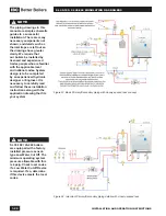
Figure 27: Two pump, two load - parallel piping concept
Summary of Contents for SL 35-199
Page 71: ...SERVICE RECORD DATE LICENSED CONTRACTOR DESCRIPTION OF WORK DONE...
Page 72: ...NOTES...
Page 73: ...NOTES...

