INSTALLATION AND OPERATION INSTRUCTIONS
4-6
SL 35-199, SL 45-260 MODULATING GAS BOILERS
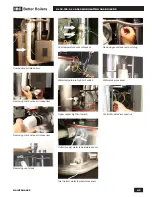
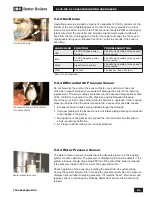
4.2.1 Fan and gas valve removal instructions
1.
Turn off electric power and gas supply to the boiler.
2.
Ensure boiler cools down to ambient temperature. Do not drain the boiler
unless freezing conditions are expected during this procedure.
3.
Remove front cover, then remove boiler upper-front cover by removing the
screws at the top right and left corner of the boiler.
4.
A ladder or step may be required to have a clear vertical view of the work
area. Do not attempt to reach from the front without a clear view, as damage
to connectors, screws or refractory may occur.
5.
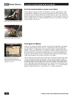
Unplug both electrical connectors from the fan.
6.
Unplug the electrical connector from the gas valve.
7.
Position the harnesses out of the way of the heat exchanger lid.
8.
Disconnect (flare-fitting) nut on flexible gas supply line.
9.
Remove the 4 - 8mm hex bolts that attach the fan to the lid and remove the
fan/gas valve assembly from the boiler.
10.
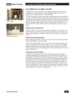
The fan and venturi are one unit and must not be separated. The gas valve
can be removed from the fan/venturi assembly by removing the three T25
Torks screws. Take care not to misplace or damage the gasket between the
gas valve and venturi.
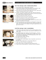
4.2.2 Fan and gas valve re-installation
1.
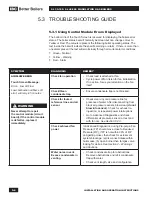
If the gas valve was removed from the venturi, ensure the gasket is in the
proper position. Attach the gas valve to the venturi and install the three T25
Torks screws.
2.
Re-install the fan/gas valve assembly onto the lid using the 4 - 8mm hex
bolts removed earlier. Ensure the black gasket is installed between the fan
outlet and the lid. Tighten the 4 hex bolts hand tight plus an extra 1/8 turn.
Test for leaks at the fan/lid gasket..
3.
Re-attach both fan harness connectors.
4.
Re-attach gas valve connector.
5.
If a new gas valve is being installed, remove the protective cover from the
gas inlet now.
6.
Re-attach the gas supply line JIC connector (flare-fitting nut).
7.
Open up gas valve and check for possible leaks.
8.
Return electric power to the boiler and perform start up routine.
9.
Check for gas or fumes leaks after 10 minutes of continuous operation.
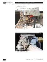
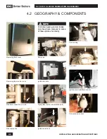
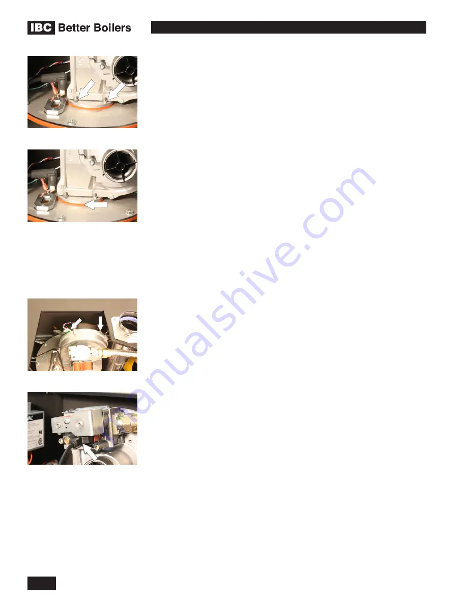
Fan mounting screws
Fan/Burner Gasket
Fan motor electrical connectors
Gas valve electrical connector
Summary of Contents for SL 35-199
Page 71: ...SERVICE RECORD DATE LICENSED CONTRACTOR DESCRIPTION OF WORK DONE...
Page 72: ...NOTES...
Page 73: ...NOTES...

