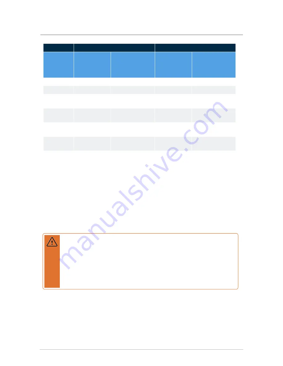
SL 26-260 G3
SL 40-399 G3
Surface
Minimum
distance from
combustible
surfaces
Recommended
distance from
installation and
service
Minimum
distance from
combustible
surfaces
Recommended
distance for
installation and
service
Front
2"
24"
2"
24"
Rear
0"
0"
0"
0"
Left side
1"
0" (non-
combustibles)
1"
0" (non-
combustibles)
Right side
1"
4" (for electric
connections)
1"
4"(for electric
connections)
Top
2"
6" (vent connection)
12"
12" (vent
connection)
Bottom
0"
12" (for condensate
trap and piping)
12"
12" (for condensate
trap and piping)
Table 4
Clearance distances for boiler mounting sites
A minimum distance below the boiler of 12" is required to provide clearance for the supplied
condensation trap assembly. More clearance will typically be required to accommodate
associated water and gas piping.
3.7 Exhaust venting and air intake
When planning a boiler's installation, consider the appropriate vent materials, travel and
termination.
Warning
Venting, condensate drainage, and combustion air systems for all IBC boilers must be
installed in compliance with all applicable codes and with instructions provided in the
respective installation manuals.
Inspect finished vent and air piping thoroughly to ensure all are airtight, and comply
with the instructions provided as well as with the requirements of applicable codes.
Failure to comply will result in severe personal injury or death.
20
Section: Installation
Summary of Contents for SL Series
Page 8: ...Intentionally left empty...
Page 12: ...Figure 5 Top view SL 40 399 G3 Figure 6 Bottom view SL 40 399 G3 8 Section Specifications...
Page 14: ...Intentionally left empty...
Page 64: ...Figure 40 Electric wiring connections 60 Section Installation...
Page 76: ...Intentionally left empty...
Page 96: ...Intentionally left empty...
Page 108: ...Intentionally left empty...
Page 110: ...Internal wiring diagram Figure 46 Internal wiring diagram 106 Section Appendices...
Page 111: ...Sequence of operations Figure 47 Sequence of Operation 107 Sequence of operations...


