ACO23/ACO234 Page 3
•
Refer all servicing to qualified service personnel. Servicing is required when the apparatus has been damaged in any
way
, such as power
-
supply cord or plug is damaged, liquid has been spilled or objects have fallen into the apparatus,
the apparatus has been exposed to rain or moisture, does not operate normally, or has been dropped.
•
POWER ON/OFF SWITCH: For products provided with a power switch, the power switch DOES NOT break the
connection from the mains.
•
MAINS DISCONNECT: The plug shall remain readily operable. For rack
-mount or installation where plug is not
accessible, an all
-pole mains switch with a contact separation of at least 3 mm in each pole shall be incorporated into
the electrical installation of the rack or building.
•
FOR UNITS EQUIPPED WITH EXTERNALLY ACCESSIBLE FUSE RECEPTACLE: Replace fuse with same type and rating only.
•
MULTIPLE
-
INPUT VOLTAGE: This equipment
may require the use of a different line cord, attachment plug, or both,
depending on the available power source at installation. Connect this equipment only to the power source indicated
on the equipment rear panel. To reduce the risk of fire or electric shock, refer servicing to qualified service personnel
or equivalent.
•
This Equipment is intended for rack mount use only.
INSPECTION
Inspect the contents of the shipping carton. Inside
both the ACO23 and ACO234 boxes you should find the following:
• Either the model
ACO23 or ACO234 crossover.
• Operation manual (you are reading it!)
• 4 rack screws and washers
• Power cord.
The contents of this manual are subject to change at any time without notice.
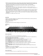
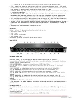
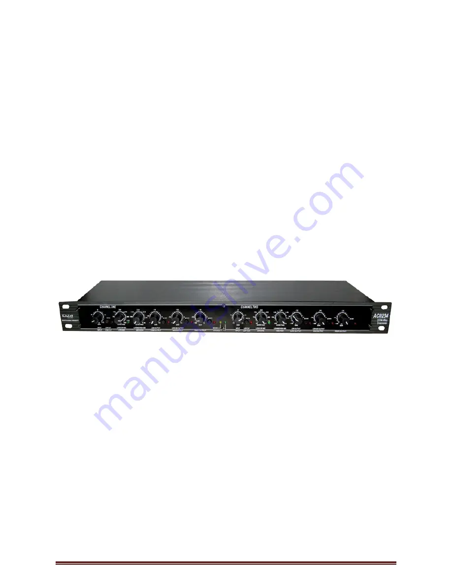
ACO234 Front
Panel
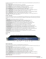
STEREO 2-WAY MODE
In 2
-way stereo mode the controls are marked BELOW the horizontal blue line.
Channel One and Channel Two functions are identical in the stereo mode. Front panel controls not described in this
section are not active in stereo 2-way operation.
[1] & [7]
INPUT GAIN
Controls the INPUT level with +/
- 12 dB of gain.
[13] & [20]
LOW CUT
Switch for selecting the 40 Hz high pass filter. An LED indicates the selection.
[2] & [8]
LOW/MID*
Selects crossover point be
tween the LOW and HIGH outputs.
[14] & [21]
X10 LED
Indicates that the LOW/HIGH crossover frequency range is 450 Hz to
9.6 kHz.
[4] & [10]
LOW OUTPUT
Controls the Low frequency output level with a range of
-
∞ to +6 dB.
[15] & [22]
PHASE INVERT
Switch for reversing the polarity on the Low Output. An LED indicates that the phase is
inverted.
[6] & [12]
HIGH OUTPUT
Controls the High frequency output with a range of
-
∞ to +6 dB.
[17] & [24]
PHASE INVERT
Switch for reversing the polarity on the High Output. An LED indicates that the phase is
inverted.
[19]
STEREO
LED indicating stereo mode operation.
* although this control is labelled as “
LOW/MID
”, it operates as the crossover frequency control between low and high
frequencies in stereo 2
-way operation.
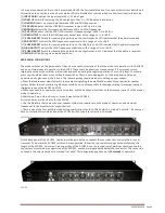
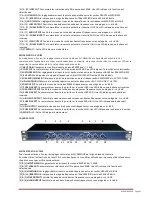
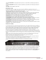
STEREO 3-WAY MODE
In 3
-way stereo operation the controls are marked BELOW the horizontal blue line.
1
2
3
4
5
6
7
8
9
10
11 12
13 14
16
19
20
21
22
23
24
18
17
15


