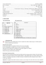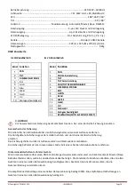
Light source: ................................................................................ 7pcs of 18W 6 in 1 LED, RGBW
A+UV
Pan: .................................................................................................................... 180°, 360°,
540
°
Tilt: ................................................................................................................................ 90°, 180°
Function: .......................................... Sound control, Auto-run, Maste
r/
Slave, DMX
512,
Strobe
Max. Ta ................................................................................................................................. 40°C
Channel: .................................................................................................10 or 1
5
DMX channels
Data input.................................................................................... Locking 3-pin XLR male socket
Data output ............................................................................ Locking 3-pin DMX female socket
Data pin configuration ................................................................. Pin1 shield, pin 2 (-), pin 3 (+)
Dimensions ..........................................................................
225
(L) x
225
(W) x 270mm (H) mm
N.W: .................................................................................................................................... 4.2kg
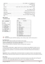
DMX Channels
In 10 channel mode
15 DMX channel mode
CH
FUNCTION
1
Pan
2
Tilt
3
Dimmer & Strobe
4
Red Dimmer
5
Green Dimmer
6
Blue Dimmer
7
White Dimmer
8
Amber Dimmer
9
UV
Dimmer
10
Motor Speed
3. SETUP
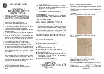
Disconnect the power cord before replacing a fuse and always replace with the same type fuse.
Fuse Replacement
With a flat head screwdriver wedge the fuse holder out of its housing.
Remove the damaged fuse from its holder and replace with exactly the same type of fuse.
Insert the fuse holder back in its place and reconnect power.
The fuse is located inside this compartment. Remove using a flat head screwdriver.
Fixture Linking
You will need a serial data link to run light shows of one or more fixtures using a DMX-
512 c
ontroller or to run
synchronized shows on two or more fixtures set to
a master/slave operating mode. The combined number of
channels required by all fixtures on a serial data link determines the number of fixtures that the data link can
support.
Important
: Fixtures on a serial
/data
link must be daisy chained in one single line. Maximum recommended serial
data link distance:
500 meters
(1640 ft.) Maximum recommended number of fixtures on a serial data link: 32 fixtures
Data Cabling
To link fixtures together you must use data cables. If you choose to create your own cable, please use data-grade
cables that can carry a high quality signal and are less prone to electromagnetic interference.
CH
FUNCTION
1
PAN
2
Pan Fine
3
TILT
4
Tilt Fine
5
Speed
6
Dimmer & Strobe
7
Red Dimmer
8
Green Dimmer
9
Blue Dimmer
10 White Dimmer
11 Amber Dimmer
12
UV Dimmer
13 Color Selection
14 Color Speed
15
MOVEMENT(AUTO & SOUND EFFECT)
©Copyright LOTRONIC 2014
LMH360LED
Page 4


